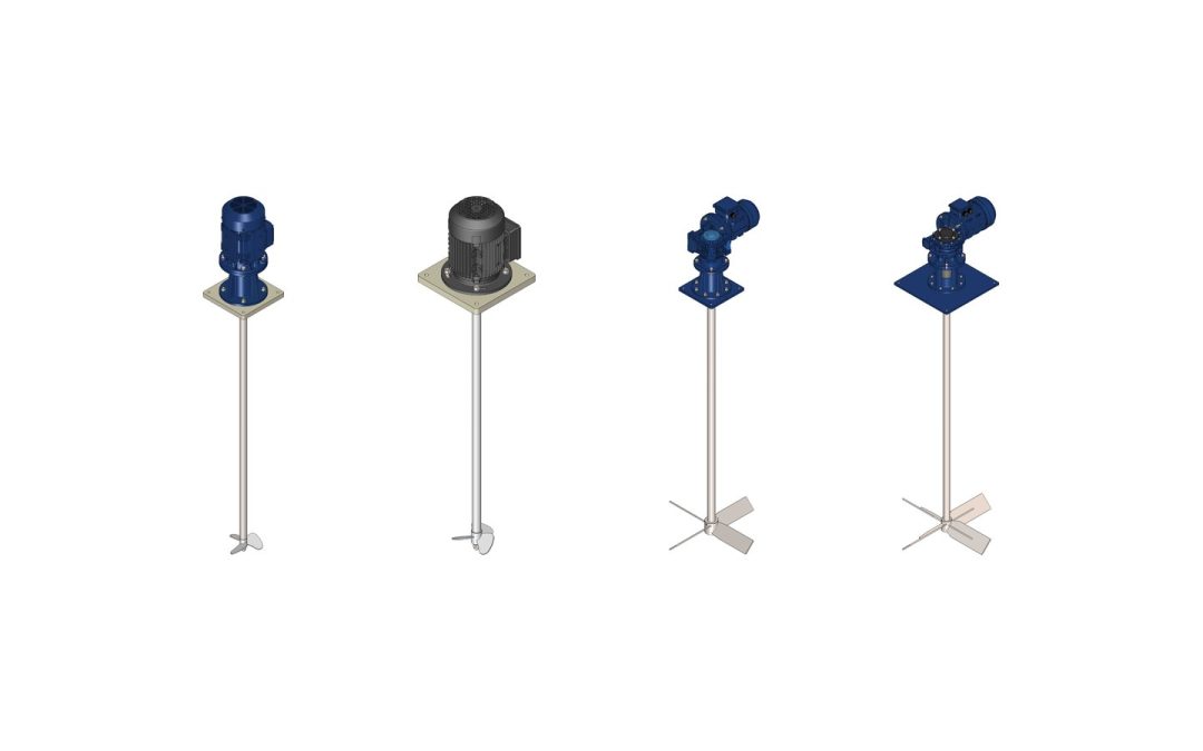
Put two agitators with the same motor and shaft into the same tank and you can still get opposite results. The difference is the impeller. Different agitator impeller types decide how the fluid moves, how much shear reaches droplets, bubbles and agglomerates, and how much motor power becomes useful mixing rather than heat and vortex.
This guide reviews the impellers we fit at Nuova Darimpianti on agitators for corrosive service: marine propeller, Cowles (cowless) disc, Rushton turbine, emulsifier, folding blades, pitched blades, high-flow, anchor and scraper. For each one we cover flow, viscosity, uses and limits. For the full agitator selection process (process objective, Reynolds number, motor), start with how to choose an industrial agitator; here we stay on the impeller.
Axial, radial and tangential flow
Every impeller pushes fluid in a dominant direction, and that direction sets the job it does well.
Axial flow
Axial impellers push liquid parallel to the shaft, usually towards the bottom. The jet rises along the walls and returns to the impeller, forming a single loop that sweeps the whole volume. This is the most efficient pattern for blending, keeping solids suspended and evening out temperature with little power. Marine propellers, pitched blades (mixed flow with an axial bias) and high-flow impellers belong here.
Radial flow
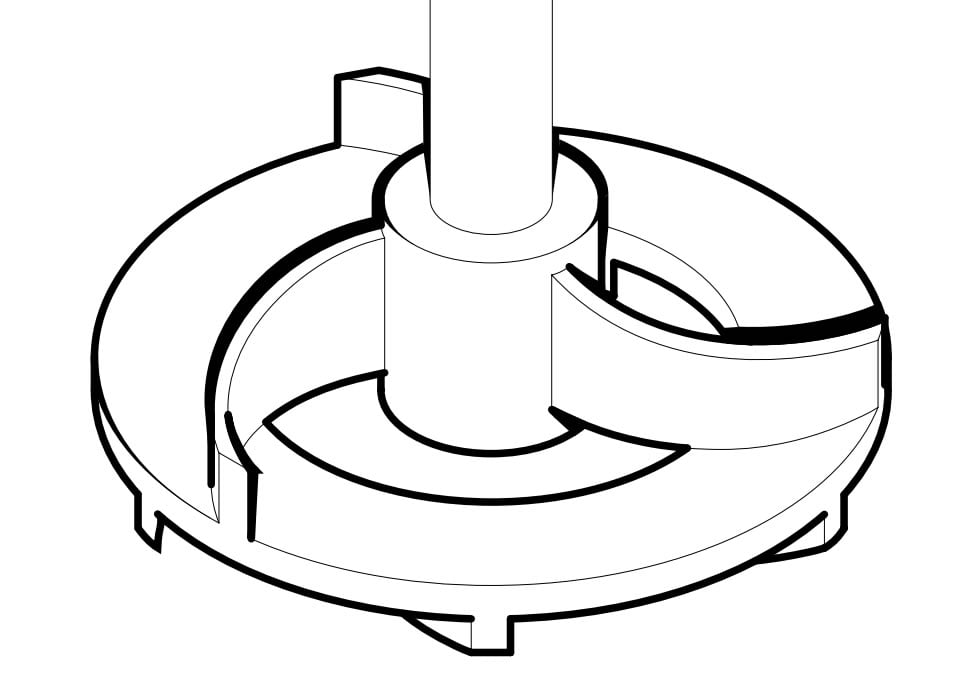
Radial impellers discharge fluid towards the walls, creating two loops above and below the impeller. They pump less liquid per kW but concentrate a lot of shear close to the blades: what you need to disperse powders and pigments, break agglomerates, emulsify or break up a gas. Cowles discs, Rushton turbines and emulsifiers are radial.
Tangential flow
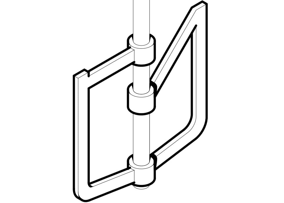
Anchors and scrapers turn slowly with a diameter close to the tank diameter, dragging the fluid round and acting continuously on the wall. You need them when the product is so viscous that a small impeller would only stir a “cavern” of liquid around itself.
In unbaffled cylindrical tanks, fast impellers tend to spin the whole liquid and pull a central vortex. The usual fixes are baffles, off-centre or angled mounting and side-entry agitators. Anchors, by contrast, run without baffles.
Agitator impeller types one by one
Speeds quoted are those on our product datasheets. Viscosity ranges are indicative and should be checked against the real fluid.
Three-blade marine propeller
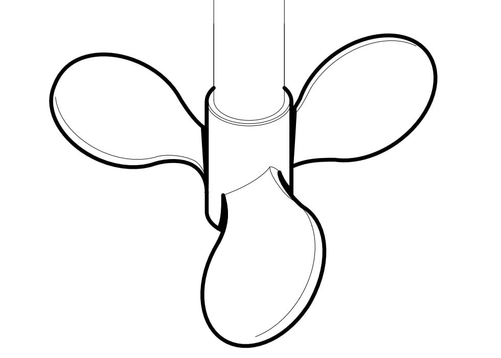
The most common impeller on fast agitators: three helical blades driving liquid towards the bottom with clean axial flow and low power. It runs from 500 to 1,500 rpm and is the standard impeller on the EV and EVK ranges.
Viscosity: low, up to about 2,000-3,000 cP.
Typical uses: diluting and neutralising acids and alkalis, preparing solutions, water treatment.
Strengths: high flow per kW, low vibration.
Limits: little shear; in viscous fluids the flow dies out near the impeller.
Cowles (cowless) disc impeller
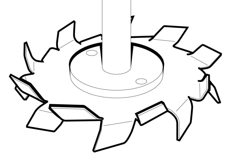
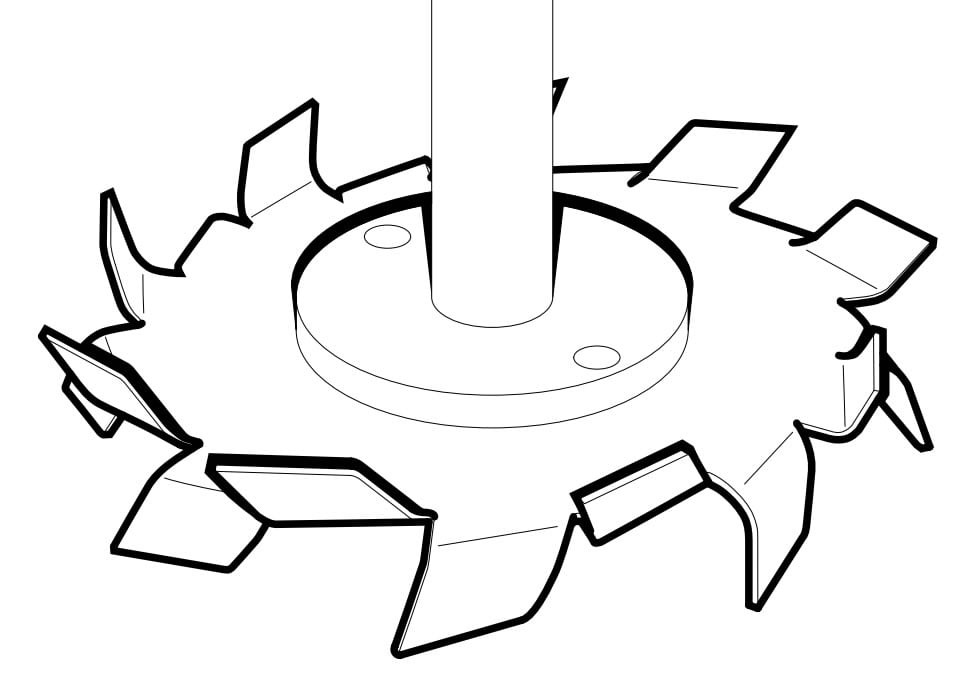
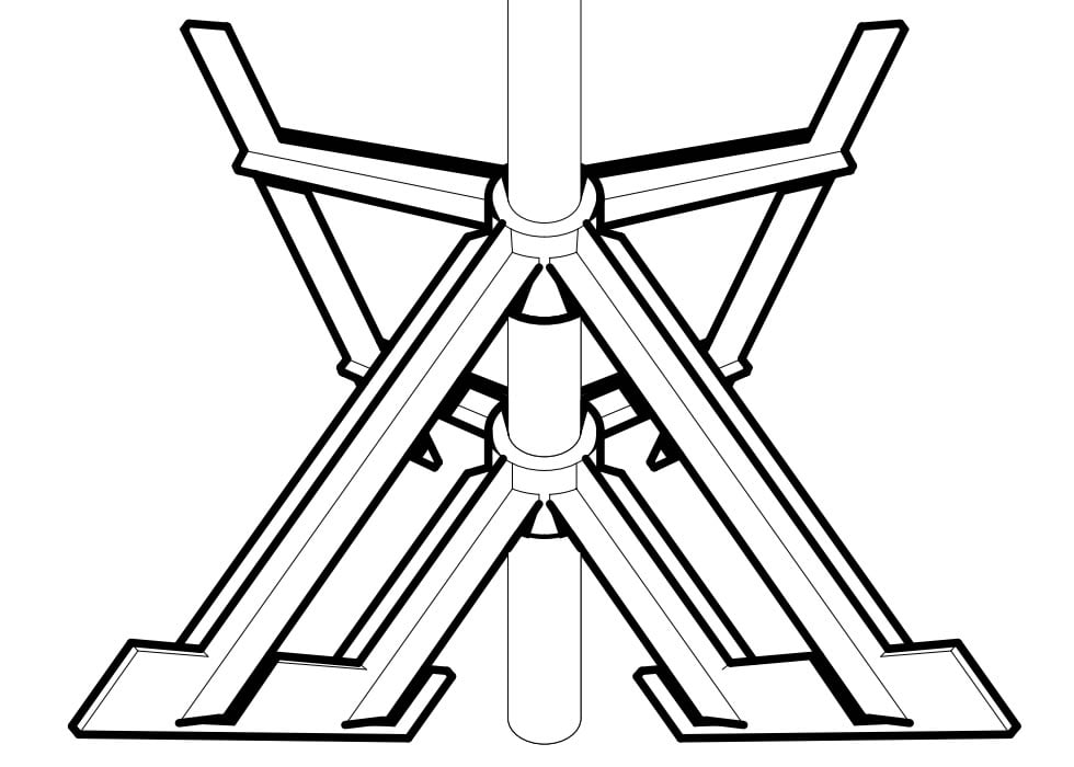
The Cowles impeller, often spelled “cowless” and also called a toothed disc or disperser blade, is a disc with teeth bent alternately up and down. At high speed it creates a very intense shear zone at the rim while product is drawn in from above and below and thrown towards the walls. It has the widest range in our line-up: 300 to 3,000 rpm. In dispersers the disc tip speed matters more than rpm (see sizing below).
Viscosity: from thin liquids to pastes of a few tens of thousands of cP, as long as product keeps flowing back to the disc.
Typical uses: dispersing pigments and fillers in paints and inks, fast powder dissolution, breaking agglomerates.
Strengths: very high shear from a simple, easy-to-clean geometry.
Limits: low pumping, so large tanks need a second circulation impeller; high power draw at top speed.
Straight-blade Rushton turbine
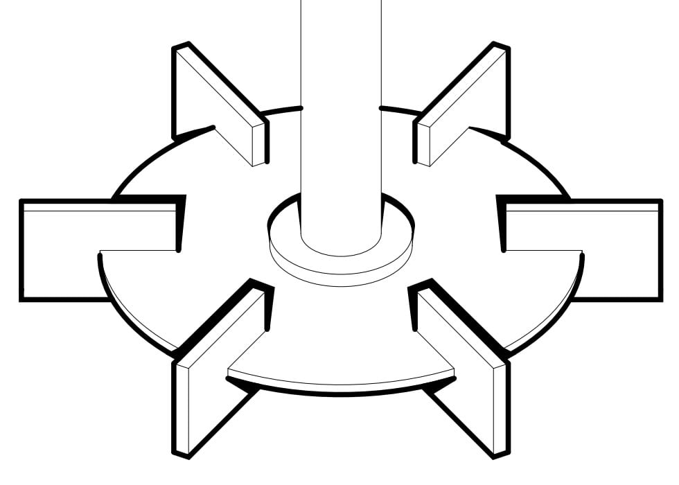
Six flat vertical blades on a disc. The disc stops gas sparged from below escaping up the shaft and forces it through the blades, where it is broken up. It runs from 300 to 1,400 rpm.
Viscosity: low to medium, below about 5,000 cP.
Typical uses: gas-liquid dispersion, reactions needing high mass transfer.
Strengths: high local turbulence, well-documented behaviour.
Limits: high power number; needs baffles; inefficient for plain blending.
Emulsifier impeller
Curved vanes inside a toothed ring: liquid enters at the centre, is accelerated and leaves through the ring, where it is sheared hard and repeatedly. It runs from 500 to 2,000 rpm.
Viscosity: low to medium.
Typical uses: emulsions of immiscible phases, fine and stable dispersions.
Strengths: smaller, more uniform droplets than an open impeller.
Limits: modest circulation; more sensitive to coarse solids.
Folding-blade (movable-blade) impellers
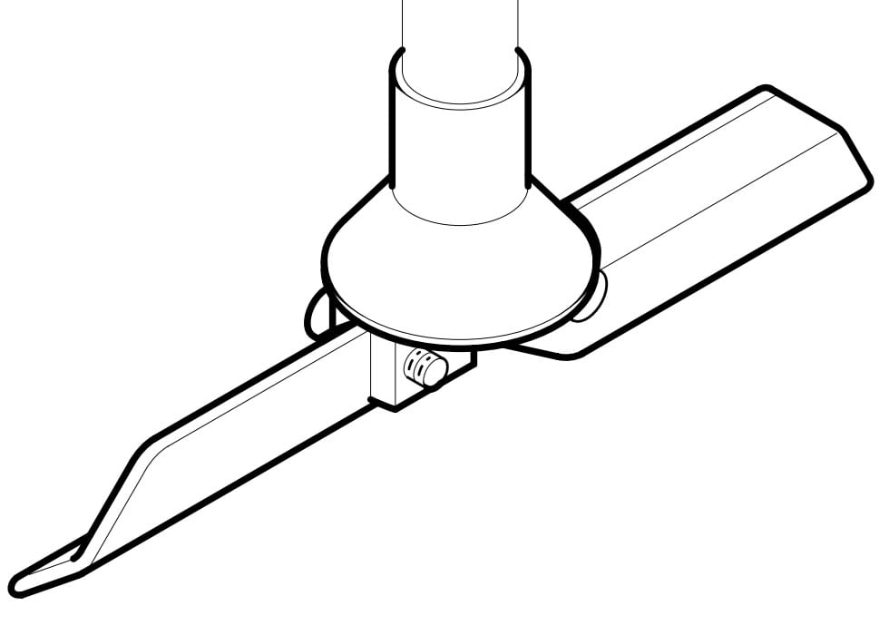
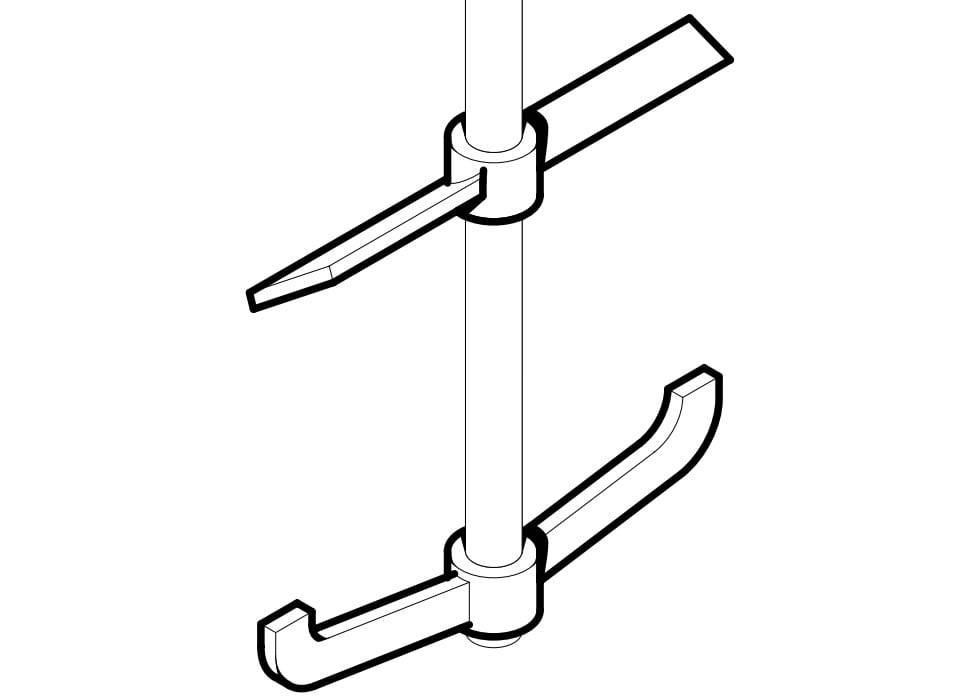
Folding-blade agitators are built for containers with a small opening, such as IBC totes and drums. The blades are pinned to the hub: in the usual arrangement they hang along the shaft when stopped, pass through the filler neck, then swing open as the shaft turns and work at full diameter. Our datasheets list the movable-blade impeller in the fast range (300-1,500 rpm) and, as a four-blade version, in the slow range (up to 400 rpm).
Viscosity: low to medium.
Typical uses: re-mixing additives and reagents in IBCs, re-suspending settled solids.
Strengths: working diameter larger than the opening; one agitator can serve several totes.
Limits: the hinge needs checking with solids-laden or crystallising fluids.
Pitched-blade turbine and modular impeller
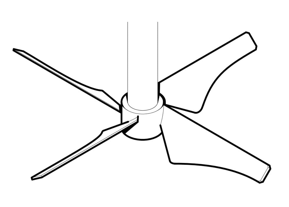
Four flat blades set at an angle, usually 45°, give mixed flow with an axial bias. It is the workhorse of slow agitators: the pitched-blade turbine and modular pitched-blade impeller run from 10 to 380 rpm. The four-blade impeller also comes with straight blades when more radial action is needed.
Strengths: versatile; several impellers can be stacked in tall tanks.
Limits: draws more power than a high-flow impeller for the same flow.
High-flow four-blade impeller
Profiled blades, wide at the root and tapering to the tip, designed to move the most volume with the least shear. It runs from 10 to 380 rpm on the EVRK, EVRL and KVRL ranges and the LRO side-entry mixer.
Viscosity: low, best below about 1,000 cP.
Typical uses: large tanks, solids suspension, flocculation where flocs must not break.
Strengths: low power number, so smaller gear motors.
Limits: loses effectiveness as viscosity rises; unsuited to dispersion.
Anchor impeller: gate anchor and anchor with paddle
The anchor follows the tank profile close to wall and bottom, turns slowly (5-56 rpm on our datasheets) and moves the whole batch by drag. The version with a paddle adds an upper arm that improves vertical turnover, the weak point of a plain anchor.
Strengths: moves the whole volume; improves heat transfer at the wall.
Limits: poor vertical exchange without extra paddles; high torque.
Scraper impeller
The scraper takes the anchor idea to its limit: arms and shoes work almost in contact with bottom and walls, removing product that sticks, settles or crystallises. We design scrapers to order around the tank and the product.
Viscosity: high, or products that build deposits.
Typical uses: fouling products, sludges that compact, wall-heated tanks.
Strengths: clean walls and bottom, steady heat transfer.
Limits: shoe wear; high power and starting torque.
Impeller comparison table
Impeller
Flow
Indicative viscosity
Speed (Nuova Darimpianti datasheets)
Typical applications
Three-blade marine propeller
Axial
Up to 2,000-3,000 cP
500-1,500 rpm
Dilution, neutralisation, water treatment
Cowles (cowless) disc
Radial, very high shear
Thin liquids to pastes
300-3,000 rpm
Pigment dispersion, powder dissolution
Rushton turbine
Radial
Below 5,000 cP
300-1,400 rpm
Gas dispersion, reactions
Emulsifier
Radial, high shear
Low-medium
500-2,000 rpm
Emulsions, fine dispersions
Folding blades
Mixed
Low-medium
300-1,500 rpm (fast); up to 400 rpm (slow)
IBCs, drums, narrow openings
Pitched blade / modular
Mixed, mainly axial
Up to about 10,000 cP
10-380 rpm
Flocculation, polyelectrolyte, plating
High-flow four-blade
Axial
Below about 1,000 cP
10-380 rpm
Large tanks, solids suspension
Anchor (gate / with paddle)
Tangential
5,000 to over 50,000 cP
5-56 rpm
Resins, gels, jacketed tanks
Scraper
Tangential with wall scraping
High or fouling
Custom design
Products that foul or settle
Sizing basics: D/T ratio, tip speed and power number
The D/T ratio
D is the impeller diameter, T the tank diameter. Typical values: 0.2-0.35 for marine propellers, 0.25-0.4 for Cowles discs and Rushton turbines, 0.3-0.5 for pitched-blade and high-flow impellers, 0.9-0.98 for anchors and scrapers. Too small a D/T leaves dead zones; too large, on a fast impeller, sends power soaring.
Tip speed
The velocity of the blade tip:
v = π · D · N / 60
with v in m/s, D in metres and N in rpm. A 150 mm Cowles disc at 3,000 rpm reaches about 23.6 m/s, typical for dispersers; a 1.5 m anchor at 20 rpm about 1.6 m/s. Tip speed is the most direct indicator of shear and the figure to watch on thermoplastic impellers, which tolerate lower tip speeds than steel.
Power number and power draw
In turbulent flow, in a baffled tank:
P = Np · ρ · N³ · D⁵
with P in watts, ρ in kg/m³, N in revolutions per second and D in metres. Np depends on geometry: about 0.3-0.5 for marine propellers and high-flow impellers, 1.2-1.5 for a 45° four-blade turbine, about 5 for a Rushton.
Example: a 0.2 m propeller at 900 rpm (15 rev/s) in water, Np = 0.35: P = 0.35 × 1,000 × 15³ × 0.2⁵ ≈ 380 W. A Rushton of the same size at the same speed takes over 5 kW. Doubling speed multiplies power by 8, doubling diameter by 32, and power scales with density: in concentrated sulphuric acid (about 1,840 kg/m³) the same agitator draws nearly twice as much as in water. The motor is then chosen with a margin over this figure. In laminar flow the formula no longer applies in this form: anchors and scrapers are sized on torque. The link between viscosity and flow regime is covered in fast vs slow agitators.
Impeller materials for corrosive service
Choose the material for the worst product the impeller will see, at the highest temperature. On our fast ranges impellers come in AISI 304-316 stainless steel or in PP, PVC or PVDF; on the slow ranges also in PE-HD, and on the KVRL they can be ebonite-coated.
PP: dilute acids and alkalis, plating baths, water treatment, up to 80-90°C.
PVC: stiff and economical, but limited to 60°C.
PVDF: concentrated acids, strong oxidisers, up to 100-120°C.
AISI 304-316: with compatible fluids, for the highest tip speeds.
Matching impellers to fast, slow and side-entry agitators
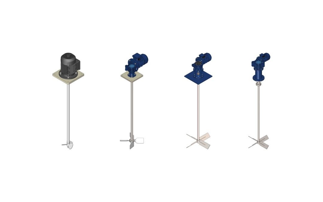
Fast agitators. On EV/EV-G and EVK the standard impeller is the three-blade marine propeller. The EVL range, with a single or double bearing lantern, and the KVL also take the straight-blade turbine, emulsifier and Cowles disc: these are the machines to choose when the impeller draws more power or runs at high tip speed.
Slow agitators. The EVR range, with the shaft keyed directly to the gearbox, carries the four-blade impeller with pitched or straight blades; EVRK and EVRL add the high-flow impeller and a lantern for medium and high loads. The KVRL, built for heavy loads, can carry 2 to 4 two-blade or four-blade impellers on one shaft, the answer for tall tanks or variable levels.
Side-entry agitators. The fast LVO takes the propeller, straight-blade turbine, emulsifier or Cowles disc; the slow LRO takes the four-blade impeller with pitched, straight or high-flow blades. Side entry suits large tanks and helps avoid a central vortex.
Frequently asked questions
What is the difference between a Cowles (cowless) impeller and a Rushton turbine?
Both produce radial flow. The Cowles disc concentrates very intense shear at the rim and is designed to disperse powders and pigments at high tip speed. The Rushton has flat blades on a disc, spreads turbulence more evenly and is the classic choice for dispersing gas into a liquid.
What are folding-blade agitators?
Agitators whose blades are hinged at the hub, so they fold to pass through a narrow opening and open as the shaft turns. They are mainly used to mix IBC totes and drums, where a rigid impeller of the required diameter would not fit through the filler neck.
Which impeller should I use for a very viscous fluid?
Above roughly 5,000-10,000 cP, small fast impellers only move the liquid around them. Use an anchor, possibly with an upper paddle, or a scraper if the product sticks to the walls. They run slowly, our anchor from 5 to 56 rpm, with gearboxes sized on torque.
Can I fit more than one impeller on the same shaft?
Yes, it is standard in tall tanks. The KVRL range takes 2 to 4 two-blade or four-blade impellers. Dispersion processes often pair a shear impeller, such as a Cowles disc, with an axial circulation impeller, to be assessed case by case.
Plastic or steel impeller?
It depends on the fluid and the tip speed. With acids, alkalis and oxidisers, PP, PVC and PVDF avoid corrosion; with compatible fluids and very high tip speeds, AISI 304-316 steel gives more mechanical margin. Often the answer is a coated steel shaft with a thermoplastic impeller machined from solid.
Conclusion: start from the flow you need
Choosing between agitator impeller types starts with one question: what has to happen in the tank? For circulation, look at axial impellers (marine propeller, pitched blade, high-flow); for shear, at radial ones (Cowles disc, Rushton, emulsifier); for thick products or fouling walls, at anchors and scrapers. Then check D/T, tip speed and power, and choose the material for the most aggressive fluid.
Choosing an impeller for a new agitator, or replacing one that underperforms? Nuova Darimpianti’s engineering team in Flero (Brescia, Italy) has been designing and building agitators and impellers in PP, PVC, PVDF and stainless steel for corrosive fluids since 1970, including custom designs. Send us your fluid, viscosity, volume and tank geometry: contact us for a no-obligation technical consultation.
Anyone who designs or runs a plant handling corrosive fluids eventually faces a very practical question: will this material withstand this chemical, at this concentration, at this temperature? This chemical resistance chart for polymers brings together the substances that come up most often in our customers’ enquiries: more than 40 combinations of acids, alkalis, oxidisers, salts and solvents, rated for polypropylene (PP), PVC and PVDF at 20 °C and 60 °C, with a room-temperature comparison against PE-HD, PTFE and AISI 316 stainless steel.
Important notice. The ratings below are indicative. They are based on general technical literature and on the compatibility charts published by manufacturers of semi-finished plastics. They refer to single substances in aqueous solution, at atmospheric pressure and without significant mechanical stress. They do not replace a check on your specific application: before choosing the material for a pump, an agitator or a tank, always confirm the data with the material supplier and the equipment manufacturer.
How to read the chemical resistance chart for polymers
Each cell combines three pieces of information: the chemical, its concentration and the temperature of the fluid in contact with the material. The rating scale is deliberately simple:
A, resistant: suitable for continuous service. Slight changes in colour or weight may occur without affecting function.
B, limited resistance: moderate attack (swelling, loss of mechanical properties, surface oxidation). It may be acceptable for short contact, unstressed parts or a shorter service life, but needs a case-by-case assessment.
C, not recommended: rapid or severe attack. Do not use.
–, insufficient data: no reliable general data, or published sources disagree. Testing is required.
Concentrations are given in percent by weight, except sodium hypochlorite, which is expressed as available chlorine as on commercial data sheets. The PVC 60 °C column sits at the material’s operating limit: even where chemical resistance is good, the mechanical margin at that temperature is small. For PE-HD, PTFE and AISI 316 we only show the 20 °C value, because they are included as reference materials rather than as the main construction materials of our pumps.
Where the sources we consulted disagreed, we chose the more cautious rating. In a chart like this, erring on the side of caution costs you a more expensive material at worst; erring on the side of optimism can cost you a plant shutdown or a product leak.
Maximum operating temperatures
Temperature matters before chemical compatibility does. A material that is chemically suitable but used beyond its thermal limit deforms, loses stiffness and becomes more vulnerable to attack by the fluid. The figures below match those in our thermoplastics guide and refer to pump and agitator components in continuous service.
Material
Max operating temperature (indicative)
Notes
PP (polypropylene)
80–90 °C
Depends on grade and mechanical load; brittle below 0 °C
PVC (polyvinyl chloride)
60 °C
Loses dimensional stability above 60 °C
PVDF (polyvinylidene fluoride)
100–120 °C
Good dimensional stability under load at temperature
PE-HD (high-density polyethylene)
60–70 °C
Less rigid than PP; good toughness at low temperature
PTFE
up to ~250 °C
Literature value; mainly used for gaskets and linings
AISI 316
not the limiting factor
Corrosion (chlorides, reducing acids) sets the limit, not temperature
For pumps, the real limit also depends on the design: our PMC-1 horizontal pumps with mechanical seal are rated for temperatures up to 80 °C, while the HTM magnetic drive pump, in PP or PVDF, and the VGA vertical pump go up to 90 °C.
Chemical resistance chart: inorganic acids
Mineral acids are where thermoplastics clearly outperform metals. Hydrochloric acid attacks stainless steel even when dilute, while PP, PVC and PVDF handle it well. Oxidising acids are a different story: concentrated nitric acid and chromic acid oxidise the hydrocarbon chains of PP and PE, and PVDF becomes the safer choice.
Chemical
Conc.
PP 20 °C
PP 60 °C
PVC 20 °C
PVC 60 °C
PVDF 20 °C
PVDF 60 °C
PE-HD 20 °C
PTFE 20 °C
AISI 316 20 °C
Sulphuric acid
≤ 10%
A
A
A
A
A
A
A
A
B
Sulphuric acid
50%
A
A
A
B
A
A
A
A
C
Sulphuric acid
96–98%
B
C
B
C
A
A
B
A
B
Oleum (fuming sulphuric acid)
–
C
C
C
C
C
C
C
A
–
Hydrochloric acid
≤ 10%
A
A
A
A
A
A
A
A
C
Hydrochloric acid
37%
A
B
A
B
A
A
A
A
C
Nitric acid
≤ 10%
A
B
A
B
A
A
A
A
A
Nitric acid
40%
B
C
B
C
A
B
B
A
A
Nitric acid
65%
C
C
C
C
A
B
C
A
A
Phosphoric acid
85%
A
A
A
B
A
A
A
A
B
Hydrofluoric acid
40%
A
C
C
C
A
A
A
A
C
Chromic acid
≤ 20%
B
C
B
C
A
A
B
A
B
A few notes on these ratings:
Concentrated sulphuric acid. At 96–98% PP tends to oxidise and darken even at room temperature; PVDF handles it at elevated temperature too. Oleum, which contains free SO3, attacks every thermoplastic in the chart.
Hydrochloric acid 37%. PP and PVC are resistant, but concentrated HCl slowly permeates through the walls. Staining on the outer surfaces of tanks and pipes, and corrosion of nearby metal parts, are common side effects.
Hydrofluoric acid. PE-HD is often preferred to PP for dilute solutions because it is less prone to stress cracking. PVC is not recommended. For high concentrations or temperatures above 40 °C, use PVDF.
Chromic acid. PP and PVC are used in chrome plating baths at moderate temperature, but service life depends heavily on concentration and temperature. That variability is why we rate them B at 20 °C and C at 60 °C.
Organic acids
Organic acids are generally less aggressive than mineral acids, with one important exception: glacial acetic acid swells PVC and should be handled in PP or PVDF.
Chemical
Conc.
PP 20 °C
PP 60 °C
PVC 20 °C
PVC 60 °C
PVDF 20 °C
PVDF 60 °C
PE-HD 20 °C
PTFE 20 °C
AISI 316 20 °C
Acetic acid
10%
A
A
A
A
A
A
A
A
A
Glacial acetic acid
≥ 96%
A
B
C
C
A
B
B
A
A
Formic acid
85%
A
B
B
C
A
B
A
A
B
Citric acid
aqueous sol.
A
A
A
A
A
A
A
A
A
Oxalic acid
aqueous sol.
A
A
A
A
A
A
A
A
B
Alkalis and caustic solutions
With strong alkalis the ranking between materials reverses. PP and PE-HD resist caustic soda and caustic potash at all common concentrations, including at elevated temperature. PVDF, despite being the most resistant material with acids, can discolour and crack in contact with hot concentrated alkalis. In concentrated caustic soda circuits above 50 °C, PP is more reliable than PVDF.
Chemical
Conc.
PP 20 °C
PP 60 °C
PVC 20 °C
PVC 60 °C
PVDF 20 °C
PVDF 60 °C
PE-HD 20 °C
PTFE 20 °C
AISI 316 20 °C
Sodium hydroxide (caustic soda)
10%
A
A
A
A
A
B
A
A
A
Sodium hydroxide (caustic soda)
50%
A
A
A
B
B
C
A
A
A
Potassium hydroxide
50%
A
A
A
B
B
C
A
A
A
Ammonia (aqueous solution)
25%
A
A
B
C
A
B
A
A
A
Calcium hydroxide (milk of lime)
slurry
A
A
A
A
A
A
A
A
A
Concentrated ammonia attacks PVC; aliphatic amines (not listed) also attack PVDF and should always be checked.
Salts, oxidisers and process solutions
Salt solutions are rarely a problem for thermoplastics. They are a problem for AISI 316: chlorides and ferric chloride cause pitting corrosion, even at room temperature. With oxidisers such as hypochlorite, hydrogen peroxide and chlorine, temperature and concentration decide everything.
Chemical
Conc.
PP 20 °C
PP 60 °C
PVC 20 °C
PVC 60 °C
PVDF 20 °C
PVDF 60 °C
PE-HD 20 °C
PTFE 20 °C
AISI 316 20 °C
Sodium hypochlorite
≤ 5% av. Cl
A
B
A
B
A
A
A
A
C
Sodium hypochlorite
12–15% av. Cl
B
C
A
B
A
B
B
A
C
Hydrogen peroxide
≤ 30%
B
C
B
C
A
B
A
A
A
Hydrogen peroxide
50%
C
C
C
C
A
B
B
A
A
Chlorine (wet gas)
–
C
C
B
C
A
A
C
A
C
Ferric chloride
saturated sol.
A
A
A
A
A
A
A
A
C
Sodium chloride (brine)
saturated sol.
A
A
A
A
A
A
A
A
B
Copper / nickel sulphate
saturated sol.
A
A
A
A
A
A
A
A
A
Demineralised water
–
A
A
A
A
A
A
A
A
A
Sodium hypochlorite. PVC is the traditional material for storage and dosing. PP works well with cold, dilute solutions, but with commercial product at 12–15% available chlorine it oxidises progressively, especially when also exposed to light.
Hydrogen peroxide. Cleanliness and the absence of metal contaminants, which catalyse decomposition, matter as much as the material. Above 30%, PVDF is the only thermoplastic in the chart with an adequate margin.
Solvents and hydrocarbons
No general rule applies to organic solvents: each chemical family has to be considered on its own. PVDF resists aromatic and chlorinated hydrocarbons very well, where PP, PE and PVC swell or dissolve, but it is attacked by ketones (acetone, MEK) and dissolves in polar aprotic solvents such as DMF and NMP, which PP tolerates.
Chemical
Conc.
PP 20 °C
PP 60 °C
PVC 20 °C
PVC 60 °C
PVDF 20 °C
PVDF 60 °C
PE-HD 20 °C
PTFE 20 °C
AISI 316 20 °C
Methanol
100%
A
A
A
B
A
A
A
A
A
Ethanol
96%
A
A
A
B
A
A
A
A
A
Isopropanol
100%
A
A
A
B
A
A
A
A
A
Acetone
100%
B
C
C
C
C
C
B
A
A
Methyl ethyl ketone (MEK)
100%
B
C
C
C
C
C
B
A
A
Ethyl acetate
100%
B
C
C
C
B
C
B
A
A
Toluene / xylene
100%
C
C
C
C
A
B
C
A
A
Dichloromethane
100%
C
C
C
C
B
C
C
A
A
Trichloroethylene / perchloroethylene
100%
C
C
C
C
A
B
C
A
A
Dimethylformamide (DMF)
100%
A
B
C
C
C
C
A
A
A
Diesel / mineral oils
–
B
C
A
B
A
A
B
A
A
Manufacturers’ charts are not consistent on ketones and esters: some rate PP as resistant to acetone at 20 °C, others as limited. We chose B. Rigid PVC is unsuitable for every solvent in the chart except the alcohols.
Factors that change chemical resistance
A chart summarises how a material behaves under standard conditions. In a real plant other factors come into play, and they can turn an A into a B, or a B into a C.
Concentration
Resistance does not always change linearly with concentration. Dilute sulphuric acid is mild for PP; at 98% it is an oxidiser. Check the actual concentration in service, including changes caused by evaporation or topping up.
Temperature
As a rule of thumb, every 10 °C rise noticeably speeds up chemical reactions and the diffusion of the fluid into the polymer. A material rated A at 20 °C can drop to B or C at 60 °C. Design for the maximum temperature reached, not the average: peaks during cleaning, exothermic dilution (sulphuric acid is the classic case) and heating cycles matter more than the nominal value.
Mixtures
The chart rates one chemical at a time. Mixtures can behave very differently: nitric acid combined with hydrofluoric acid, sulphuric acid with oxidisers, or an acid solution containing traces of solvent can attack a material that resists each component on its own. Mixtures need a dedicated assessment and, for critical processes, an immersion test.
Mechanical stress and stress cracking
A loaded component (a rotating impeller, a shaft, a bolted flange) is more vulnerable than an unstressed test specimen. Environmental Stress Cracking, the cracking caused by stress and fluid acting together, mainly affects polyolefins in contact with surfactants, alcohols and some oxidisers. Residual stresses in moulded parts make the problem worse; this is why the critical components of our pumps are machined from solid, as explained in our article on solid block CNC machining.
Permeation
Some small molecules, such as HCl, chlorine, bromine and certain solvents, slowly pass through polymer walls without visibly degrading them. Permeation does not necessarily damage the plastic part, but it can corrode external metal parts (bolts, frames, motors) or contaminate the fluid. Thicker walls and fluoropolymers reduce it.
Seals and elastomers
The chart covers structural materials. In a pump the weakest link is often the O-ring or the seal: a PVDF casing with an incompatible gasket will still leak. Elastomers (FKM, EPDM) and PTFE must be selected with the same care, using their own compatibility charts.
From the chart to pump and agitator selection
The chart is a first screening tool. In practice the final choice also weighs cost, availability of semi-finished stock, mechanical loads and expected service life. Some practical pointers:
For dilute acids and alkalis at moderate temperature, PP covers most applications. It is the base material of our horizontal and vertical pumps.
For hypochlorite and cold applications where stiffness is needed, PVC remains a sound choice.
For concentrated acids, strong oxidisers, hydrofluoric acid and temperatures up to 100–120 °C, move to PVDF.
For agitators, the shaft can be AISI 304-316 stainless steel or steel coated with PP, PVC, PVDF or PE-HD. With chloride-rich fluids or reducing acids, the thermoplastic coating protects the steel, as on our EVL fast mixers.
For heating and cooling aggressive fluids we build heat exchangers in PP, PE, PVDF and PVC, as part of our special equipment range.
If your fluid is an acid, you will find guidance on pump configuration (single seal, double seal or magnetic drive) in our guide to pumps for corrosive acids. For surface treatment baths, where acids, metal salts and high temperatures coexist, see also our article on agitators for electroplating.
Frequently asked questions
What is the difference between “limited resistance” and “not recommended”?
With limited resistance (B) the material suffers moderate attack: it may swell, lose some mechanical properties or discolour. It can be acceptable for occasional contact or lightly stressed parts, but service life is shorter and must be assessed case by case. Not recommended (C) means rapid or severe attack: do not use the material under those conditions.
Is PVDF always the safest choice?
No. PVDF is the most resistant material with strong acids, oxidisers, aromatic and chlorinated hydrocarbons, but it resists hot concentrated alkalis less well than PP and is attacked by ketones, amines and solvents such as DMF and NMP. It also costs several times more than PP. Specify it when it is genuinely needed.
Can I use the chart for a mixture of chemicals?
Only as a first indication. Mixtures can be more aggressive than their individual components, for example nitric acid with hydrofluoric acid, or acids in the presence of oxidisers. A mixture needs a specific assessment and, in critical processes, an immersion test under real operating conditions.
Why does AISI 316 stainless steel rate worse than plastic with some acids?
AISI 316 relies on a passive oxide layer that holds up well in oxidising environments such as nitric acid, but is broken down by reducing acids (hydrochloric, dilute sulphuric) and by chlorides, which cause pitting. Under those conditions PP, PVC and PVDF last longer and cost less than special alloys.
How do I check compatibility for a specific application?
You need the fluid composition and concentration, minimum and maximum temperature, any suspended solids, the duty (continuous or intermittent) and the components involved. With that information the material suppliers’ charts can be cross-checked and, if the case is borderline, an immersion test carried out. Our technical department can run this check with you.
Check the material before you order
A chemical resistance chart narrows down the options quickly, but the final answer depends on the real application: fluid, concentration, temperature, mechanical loads and type of machine. In Flero (Brescia, Italy), Nuova Darimpianti designs and builds pumps and agitators in PP, PVC, PE-HD and PVDF machined from solid, with stainless steel or coated shafts, and has been helping customers choose the right material for decades.
Have a fluid to handle and not sure about the material? Contact our technical department with the chemical, concentration and temperature, and we will help you check compatibility and select the right pump or agitator.
Every plant that uses acids or alkalis has to move them somewhere. Sulphuric acid leaves a bulk tank and ends up in a neutralisation pit; caustic soda is drawn from storage and metered into a pH control loop; ferric chloride is pumped from an IBC to a flocculation tank. Chemical dosing and transfer systems are the pumps, tanks, pipework, valves and instruments that do this work. Specified well, they run for years with little attention. Specified badly, they produce a steady stream of failed seals, cavitating pumps, corroded floors and operators exposed to acid fumes.
This guide is written for process engineers, plant managers and buyers who need to specify, upgrade or replace a system for withdrawing, transferring and dosing corrosive liquids. It covers the main components, how to match materials to the chemical, the design choices that keep leaks under control, and the data you need before asking for a quote. The last section explains how Nuova Darimpianti, based in Flero near Brescia, Italy, designs and builds these systems to order, from a single pump to a complete skid.
What chemical dosing and transfer systems do
Three functions are usually involved, often in the same installation:
Withdrawal: taking liquid out of a storage tank, pit or drum.
Transfer and recirculation: moving it to a day tank, a process vessel or a treatment line, or keeping it circulating through a filter, heat exchanger or scrubber.
Dosing: injecting a controlled quantity of chemical into a process, for example acid for pH correction, caustic for neutralisation, or coagulant and polyelectrolyte for water treatment.
A typical layout therefore includes a storage tank, a transfer pump, sometimes a make-up tank with an agitator where the chemical is diluted or dissolved, a dosing pump, the valves and instruments that protect each item, and secondary containment around the whole lot. Where the chemical gives off fumes, tank vents are routed to an abatement system.
The difference from an ordinary water circuit is the fluid. A concentrated acid attacks metals, swells the wrong elastomers and turns a small drip into a safety incident. Every wetted part has to be compatible with the chemical, and the layout should keep the number of potential leak points as low as possible.
The main components
Withdrawal from tanks: vertical immersion pumps
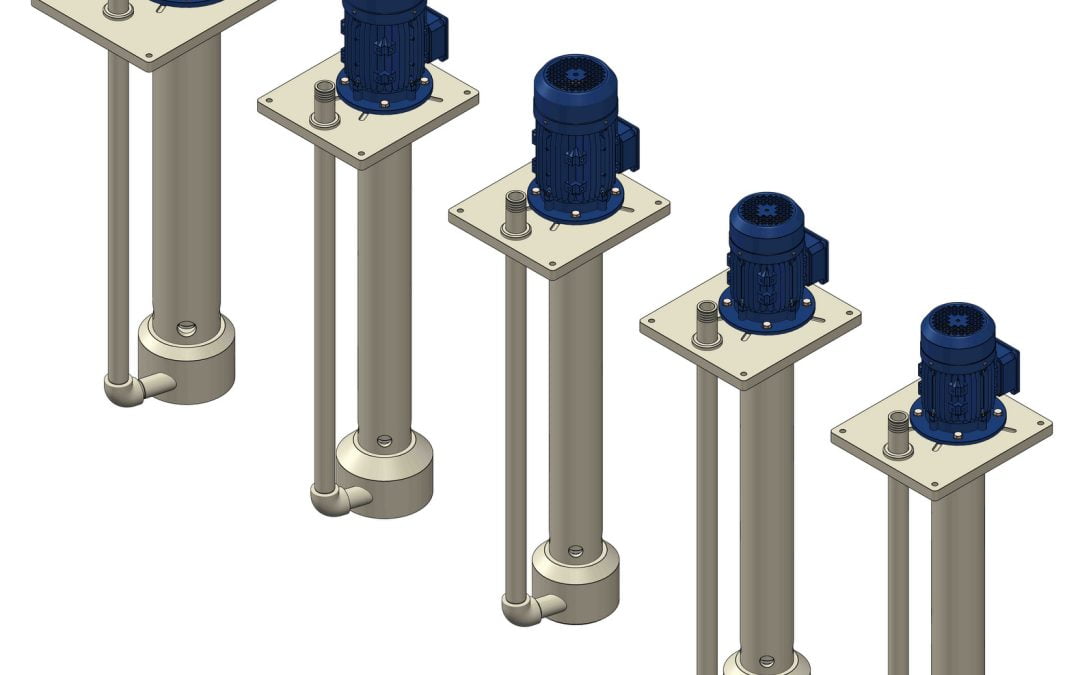
For drawing liquid from an open-top tank or pit, the usual answer is a vertical centrifugal pump. The pump casing sits submerged in the liquid while the motor stays above the rim, so the pump is always flooded, needs no priming and has practically no suction line. That removes the most common cause of cavitation (suction-side losses) along with a whole set of flanges and fittings that could leak.
Nuova Darimpianti builds several vertical pumps entirely in thermoplastic, with no metal parts in contact with the pumped liquid:
The VSK vertical pump is made of PP, PVC or PE for temperatures up to 80 °C. Its cantilever motor shaft has no connections and no shaft guide, which keeps maintenance very simple.
The VGA vertical pump is available in PP, PVC or PVDF for temperatures up to 90 °C, with a ceramic bush guiding the shaft end.
The VL/VLK vertical pump has a mechanical support with aluminium lantern and bearing, an elastic coupling between motor and pump and a ceramic guide bush. Above 2000 mm length it uses a double ceramic guide, which makes it the model for deep tanks.
The vertical range also handles liquids carrying solids or with moderate abrasiveness, which is common in neutralisation pits and spent plating baths.
When large volumes of corrosive liquid have to be recirculated at low head, for instance on a scrubber or during bulk decanting, the EVFA-N external vertical flushed pump is worth considering. Built in polypropylene, it runs with a low-speed motor (1450 rpm) suited to continuous duty, and its mechanical seals are flushed with clean water so they stay in good condition even with very aggressive liquids. A single-seal version without external flushing is also available.
Transfer and recirculation: horizontal centrifugal pumps
If the pump must sit outside the tank, for example to feed several users from one storage tank or to draw from a closed vessel under flooded suction, a horizontal centrifugal pump is used. The key decision is how the shaft is sealed.
The HTM magnetic drive pump, in PP or PVDF for temperatures up to 90 °C, has no mechanical seal at all. Torque reaches the impeller through a magnetic coupling across a sealed separator, so there is no dynamic seal to wear and leak. It is the natural choice for hazardous chemicals where no emission is acceptable; our guide to magnetic drive pumps covers the trade-offs in detail.
The PMC-1 and PMC-2 horizontal pumps use a mechanical seal, single or double flushed; the PMC-2 is a close-coupled design for high flow rates. A double flushed seal puts a barrier between the process fluid and the surroundings.
Dosing and flow control
Accurate dosing is normally done with positive displacement metering pumps (diaphragm or piston), which deliver a fixed volume per stroke and are adjusted by stroke length or frequency. For larger, less critical flows, a centrifugal pump on a variable speed drive can do the job, with the control loop closed on a flow meter or directly on the process measurement, such as pH.
Whatever the technology, three points matter when dosing acids: chemical compatibility of the pump head and check valves, stable delivery across the range of back-pressures, and a pressure relief valve on the discharge. The metering pump itself is selected project by project, according to the chemical, the flow range and the injection point.
Tanks and make-up vessels
The tank is the largest item in most systems. Nuova Darimpianti manufactures polypropylene tanks reinforced with steel frames, including large-capacity units, intended for containing highly corrosive liquids.
When a chemical has to be diluted, dissolved or kept uniform, the make-up tank needs an agitator. Nuova Darimpianti’s mixers for corrosive environments are used in polyelectrolyte preparation, flocculation, neutralisation and physical-chemical water treatment plants, among other duties.
Valves, pipework and instruments
A dependable system needs at least:
isolation valves on both sides of each pump, so it can be taken out of service safely;
check valves on the discharge and, on dosing lines, back-pressure and relief valves;
level indication or transmitters on each tank, with a low-level alarm to protect pumps from running dry and a high-level alarm to prevent overfilling;
pressure gauges fitted with diaphragm seals, so the corrosive fluid never reaches the instrument;
pipework and fittings in the same thermoplastic as the pump, or another compatible material, properly supported and allowing for thermal expansion.
Matching materials to the chemical
Chemical compatibility comes first. Polypropylene (PP), PVC and PVDF are the three thermoplastics found most often in dosing and transfer systems for corrosive fluids, and each has its own operating window. The table below gives common general guidance; final selection must always take concentration, temperature and any oxidisers or impurities into account.
Chemical
Materials usually suitable
Design notes
Hydrochloric acid
PP, PVC, PVDF
Fumes readily: pay attention to vapour seals and tank venting
Dilute sulphuric acid
PP, PVC
Consider PVDF at higher concentrations
Concentrated sulphuric acid
PVDF
Dilution releases a lot of heat: design the mixing step carefully
Sodium hydroxide (caustic soda)
PP
PVDF is not always suitable with hot strong alkalis: check case by case
Sodium hypochlorite
PVC, PVDF
Oxidising: check elastomer compatibility
Ferric chloride, polyelectrolytes
PP, PVC
Typical in water treatment; watch for crystallisation
Nitric acid
PVDF
Strong oxidiser: polyolefins are limited at higher concentrations
O-rings and gaskets deserve the same care. As a rule of thumb, FPM suits many acids, EPDM suits alkalis, and PTFE is the safest all-round choice when the chemical changes or compatibility is uncertain.
Designing out leaks and exposure
Safety is far cheaper to build in at the design stage than to retrofit. The principles are straightforward.
Fewer leak points. Every flange, fitting and seal is a potential leak. Vertical immersion pumps eliminate the suction line; magnetic drive pumps eliminate the mechanical seal. Where a seal is unavoidable, a double flushed seal adds a second line of defence.
Secondary containment. Tanks and pumps should stand in a bund sized for the largest tank, made of or lined with a compatible material. For particularly hazardous chemicals, double-wall tanks with interstitial leak monitoring are common practice. Exact requirements depend on local regulations and on how the substance is classified.
Pump protection. Low-level alarms, dry-running protection and relief valves on positive displacement circuits prevent the most serious failures. A pump damaged by running dry is often where a leak starts.
Fume control. Hydrochloric acid, nitric acid and many plating baths release corrosive and toxic vapours. Tank vents and extraction hoods should be ducted to an abatement system. Nuova Darimpianti builds static-bed and floating-bed abatement scrubbers, from design through to installation.
Sizing: the data you need
Collect this information before requesting a quotation:
Chemical and concentration, with the safety data sheet, any solids or crystals, and viscosity.
Temperature: minimum, normal and maximum.
Flow rate for withdrawal or transfer, and for dosing the turndown range required.
Head: elevation differences, pipe length and diameter, pressure at the injection point. Our guide to pump head and flow calculation walks through the method.
Tank geometry: depth, minimum draw-off level, nozzle arrangement. This sets the immersion length of a vertical pump.
Duty: continuous or intermittent, number of starts per hour, need for a standby pump.
Installation: indoor or outdoor, hazardous area classification, available footprint, power supply.
A common mistake is oversizing “to be safe”. In transfer duty this pushes the pump away from its best efficiency point, with more vibration and faster wear. In dosing it leaves the metering pump running near the bottom of its range, where accuracy is poorest.
Typical applications
Industry
What the system does
Typical components
Water and wastewater treatment
pH correction, flocculation, neutralisation
Make-up tanks with agitators, dosing of acids, alkalis and polyelectrolyte
Electroplating and surface finishing
Bath top-up and recirculation, transfer to effluent treatment
Vertical immersion pumps, magnetic drive pumps, filters
Chemical processing
Reagent storage and transfer, reactor feed
PP tanks, horizontal pumps with double seals or magnetic drive
Air pollution control
Recirculating scrubbing liquor, reagent dosing
High-flow, low-head pumps, dosing of neutralising agent
How Nuova Darimpianti builds custom systems
Alongside individual components, Nuova Darimpianti designs and builds complete skid-mounted plants for treating chemicals and water. Each skid is designed to the customer’s specification, on a stainless steel, painted iron or plastic-coated frame, and comes complete with pumps, tanks, agitators, filters, heat exchangers and pipework, with an electrical control panel on request. Because the system arrives pre-assembled, site work is reduced to a few connections.
Projects start in the in-house engineering office, which takes them from specification to construction, including systems for conveying and pumping aggressive and hazardous products. With 3- and 5-axis machining centres, lathes and milling machines, pumps, agitators and custom parts are machined from solid thermoplastic.
The wider special equipment range covers PP, PE, PVDF and PVC heat exchangers, filter units, oil separators and abatement scrubbers. Once the system is running, the in-house workshop provides routine and extraordinary maintenance on the pumps, agitators and parts supplied.
Frequently asked questions
What is the difference between a transfer system and a dosing system?
A transfer system moves liquid from one tank, pit or drum to another point, and its main requirement is flow. A dosing system injects a controlled amount of chemical into a process, and its main requirement is accuracy. In most plants the two are linked: a transfer pump fills a day tank, and the metering pump draws from it.
When should I use a vertical pump to withdraw chemicals from a tank?
Whenever you are drawing from an open-top tank or pit. A vertical pump works with its casing submerged, needs no priming and has no suction line, which reduces both cavitation risk and the number of leak points. Models such as VSK, VGA and VL are chosen according to tank depth, chemical and temperature.
Which material is best for dosing sulphuric acid?
It depends on concentration and temperature. PP and PVC are commonly used for dilute solutions, while PVDF is generally the safer choice for concentrated acid. Elastomers should be checked just as carefully as the pump body.
How do I prevent leaks in an acid transfer system?
Reduce the number of leak points (vertical pumps, magnetic drive pumps, double flushed seals), install tanks and pumps inside a bund, protect pumps from dry running with level alarms, and fit isolation valves so maintenance can be done safely.
Does Nuova Darimpianti supply complete systems or only components?
Both. Pumps, agitators, tanks and other components are available individually, and the company also designs and builds complete skid-mounted plants for chemical and water treatment, with an electrical panel on request.
Conclusion
Chemical dosing and transfer systems for corrosive fluids work best when every decision starts from the chemical: wetted materials, pump and seal type, containment and fume handling. Sourcing pumps, tanks, agitators and skid assembly from a single supplier also cuts down the interfaces you have to manage.
Planning a new chemical dosing or transfer system, or upgrading an existing one? The engineering team at Nuova Darimpianti can help you select pumps and materials and design the complete installation. Contact us for a no-obligation technical consultation.
The electroplating industry is one of the most aggressive environments for any mechanical component immersed in a treatment tank. Chromic acid solutions at 60°C, pH-controlled nickel plating baths, pickling solutions with hydrochloric and hydrofluoric acid, hot alkaline degreasing baths: each tank presents a different combination of chemical aggressiveness, temperature and mixing requirements.
An inadequate agitator in an electroplating tank does not simply perform poorly — it compromises the quality of the electrodeposit. Insufficient mixing causes non-uniform ion distribution, hot and cold zones in the tank, accumulation of contaminating metal ions near the cathode, and surface defects on the workpiece (porosity, burning, coating delamination).
This guide analyses the specific agitation requirements for each stage of the electroplating process and explains how to select the correct agitator for every type of bath.
Why agitation is critical in electroplating processes
In an electroplating bath, metal deposition occurs through electrochemical reduction of metal ions on the cathode surface (the workpiece to be coated). Deposit quality depends directly on three factors that agitation controls.
Uniform ion distribution
During deposition, metal ions are consumed near the cathode, creating a depleted zone (diffusion boundary layer). If the solution is not adequately agitated, the ionic concentration near the workpiece drops below the critical level and the deposit becomes porous, rough or non-uniform. Agitation constantly renews the boundary layer, maintaining uniform ionic concentration across the entire workpiece surface.
Temperature uniformity
Many electroplating baths operate at controlled temperatures: chrome plating at 50–60°C, nickel plating at 45–55°C, alkaline zinc at 25–35°C. Heating elements or coils create thermal gradients that, without agitation, can reach 5–10°C between different zones of the tank. This non-uniformity causes differences in deposit thickness, aesthetic defects and variations in coating mechanical properties. The agitator maintains temperature uniformity within ±1–2°C.
Gas bubble removal
During electrolysis, hydrogen gas evolves at the cathode. If hydrogen bubbles adhere to the workpiece surface, they prevent metal deposition at those points, creating porosity (pitting). Agitation promotes bubble detachment and removal, improving the surface quality of the deposit.
The effect on cathode efficiency
Agitation has a direct impact on process efficiency. In a chrome plating bath, cathode efficiency with agitation reaches 70–90%, while without agitation it drops to 50–60%. This means that for the same treatment time, the agitated workpiece receives a significantly thicker and more uniform deposit.
Electroplating baths: specific requirements for each treatment type
Each stage of the electroplating cycle has different agitation needs. Let us examine the main ones.
Alkaline degreasing
Degreasing is the first stage of the cycle and uses strongly alkaline solutions (NaOH 30–50 g/l, carbonates, phosphates, surfactants) at temperatures of 50–80°C. Agitation must be vigorous to promote detachment of organic contaminants from the workpiece surface, keep surfactants in emulsion and ensure uniform cleaning across the entire surface.
For this stage, a high-speed EV series agitator with a three-blade marine propeller impeller in PP is the standard choice. The high speed generates the turbulence needed to “strip” oily residues from the metal surface.
Acid pickling
Pickling removes oxides and scale from the surface through immersion in strong acids: 10–20% hydrochloric acid (the most common), 10–25% sulfuric acid, or hydrochloric/hydrofluoric acid blends for stainless steels.
Agitation must be moderate: sufficient to maintain uniform acid concentration and remove reaction products (metal salts) from the surface, but not so violent as to cause excessive base metal removal. The EVR series with pitched blade impeller at low speed (50–150 rpm) is ideal: it generates recirculation without excessive turbulence.
For baths with hydrofluoric acid, the material must be PVDF. For dilute hydrochloric and sulfuric acid, PP is adequate.
Alkaline zinc bath
Alkaline zinc plating uses sodium zincate solutions in a strongly alkaline environment (NaOH 80–140 g/l) at ambient or slightly heated temperature (25–35°C). Agitation must be gentle and uniform to avoid localised turbulence that would cause non-uniform deposits.
A low-speed EVR or KVRL series agitator at 30–80 rpm with PP pitched blade impeller is ideal. PP has excellent resistance to caustic soda, even concentrated — one of the few applications where PP outperforms PVDF.
Nickel bath (Watts)
The Watts bath (nickel sulfate, nickel chloride, boric acid) operates at 45–55°C and pH 3.5–4.5. Agitation must be uniform and low-turbulence to prevent air incorporation and ensure a bright, pit-free deposit.
The EVR series at 40–100 rpm with PP impeller is the typical configuration. For electroless nickel baths that operate at 85–90°C with more aggressive pH, PVDF offers greater reliability.
Chrome plating bath
Chrome plating is the most critical electroplating process from both the agitation and materials standpoint. The bath contains chromic acid (CrO₃ 200–400 g/l) and sulfuric acid as catalyst, at temperatures of 50–60°C.
Chromic acid is a strong oxidiser that attacks both PP and PVC. PVDF is the only adequate thermoplastic material for agitators immersed in chrome plating baths.
Agitation must be moderate and uniform: sufficient to maintain homogeneous temperature and constant ion distribution, but without excessive turbulence that would promote evaporation of chromium compounds (an environmental and health concern). The EVR or KVRL series with PVDF impeller at 30–60 rpm is the optimal configuration.
Acid copper bath
Acid copper plating (copper sulfate in sulfuric acid) operates at ambient temperature with H₂SO₄ concentrations of 5–10%. Agitation must be vigorous near the cathodes to uniformise ion distribution, especially on workpieces with complex geometries (holes, recesses, corners).
The EV series with PP impeller at medium-high speed (300–800 rpm) provides the turbulent flow needed. For plants with large tanks, side-entry agitators from the LVO series may be preferable.
Rinsing and washing
Rinse tanks between process stages require vigorous agitation to rapidly remove chemical drag-out from the workpiece surface. High-speed EV series in PP, with the possibility of multiple installations for large tanks.
Installation configurations for electroplating tanks
Electroplating tanks have specific geometries (typically rectangular, long and narrow) that require particular installation solutions.
Top-entry installation
Top-entry installation is the most common for small and medium tanks. The agitator is mounted on the tank rim with a bracket support. The shaft descends vertically into the solution with the impeller positioned in the lower third of the tank.
For electroplating tanks, Nuova Darimpianti offers the EVL and EVRL series with extended shafts, specifically designed to reach the bottom of deep tanks without requiring intermediate guides.
Side-entry installation
For long tanks where a single top-entry agitator cannot guarantee uniformity along the entire length, side-entry installation (LVO or LRO series) generates a helical flow involving the entire volume. This configuration is particularly effective for electroplating lines with tanks 2–5 metres in length.
Multiple installation
For very large tanks or processes requiring particularly uniform agitation, multiple agitators can be installed on the same tank, distributed evenly along the length. In this case, it is important that the impellers generate complementary (not opposing) flows to avoid zones of excessive turbulence or dead zones.
Fume resistance: an often-overlooked aspect
In hot electroplating tanks, the zone immediately above the liquid level is exposed to concentrated acid fumes and vapours. The agitator shaft passes through this zone and suffers chemical attack that is different from — and often more aggressive than — the attack in the solution.
Chromic acid fumes, for example, attack PP even when the solution below would not (because the fumes are more concentrated and oxidising). For this reason, in chrome plating tanks it is advisable to use PVDF also for the exposed portion of the shaft, or to provide a protective sleeve in the liquid-vapour interface zone.
Agitator maintenance in electroplating environments
The electroplating environment is particularly aggressive for maintenance. Here are the recommended practices.
The impeller and shaft should be visually inspected every 3–6 months for signs of chemical attack (whitening, surface roughness, swelling). Bath concentration and temperature must be constantly monitored: a concentration drift can shift the fluid outside the material’s compatibility zone. Bearings and seals (in gear-reducer versions) must be protected from acid vapours with bellows or sleeves.
Thanks to solid-block CNC machining, Nuova Darimpianti components have no internal stresses that could accelerate chemical degradation: this translates to longer service life compared to moulded components, especially in cyclic environments (tanks heated and cooled daily).
Frequently asked questions
What agitation speed is needed for an electroplating tank?
It depends on the bath type. For chrome and nickel plating, low speeds (30–100 rpm) with pitched blade impellers are ideal to avoid excessive turbulence. For degreasing and rinsing, higher speeds (300–800 rpm) with propeller impellers promote mechanical cleaning. The guiding principle is: deposition baths → low speed; preparation baths → high speed.
Can I use compressed air instead of a mechanical agitator?
Air agitation is a traditional alternative, but has disadvantages: it introduces oxygen into the bath (problematic for many processes), creates acid mists above the tank, does not allow precise control of mixing intensity, and has lower energy efficiency. Mechanical agitators offer more precise control and better efficiency, and are preferred in modern plants.
Which material should I use for an agitator in a chrome plating tank?
PVDF is the only adequate thermoplastic material for chrome plating baths. Chromic acid is a strong oxidiser that attacks both PP and PVC. PVDF resists chromic acid at all concentrations and operating temperatures of chrome plating (50–60°C).
Can the agitator damage workpieces in the tank?
If the impeller is too close to the workpieces hung on the cathode frame, excessive flow can cause non-uniform deposits on exposed edges (the “dog bone” effect). The impeller should be positioned at least 15–20 cm from the workpieces, in the lower third of the tank, where it generates circulation without directly impinging on the cathode surfaces.
Does Nuova Darimpianti supply agitators for complete electroplating lines?
Yes. Nuova Darimpianti designs agitation solutions for the entire electroplating line: degreasing, pickling, deposition baths, rinses and post-deposition treatments. Each tank is individually analysed for size, fluid, temperature and process objective, with personalised selection of series, material and speed.
The right agitator for every stage of the electroplating cycle
The quality of an electroplating treatment depends on many factors, but agitation is one that is too often underestimated. A correctly sized agitator built from the right material improves deposit uniformity, reduces rejects, increases cathode efficiency and extends bath life.
Nuova Darimpianti manufactures high-speed agitators (EV, EVK, EVL, KVL series) and low-speed agitators (EVR, EVRK, EVRL, KVRL series) in PP, PVC and PVDF specifically designed for the electroplating and surface treatment industry. Every component is machined from solid blocks on CNC centres to guarantee maximum chemical resistance and durability even in the most aggressive baths.
Planning a new electroplating line or looking to improve agitation in existing tanks? Contact Nuova Darimpianti’s engineering team for personalised advice.
Transferring corrosive liquids from drums, IBC totes and industrial containers is a daily operation in every chemical plant, electroplating facility and water treatment works. It is also one of the most hazardous operations when performed without the correct equipment: tilting a 200-litre drum of sulfuric acid is dangerous for operators and can cause spills with severe environmental and legal consequences.
Drum transfer pumps solve the problem at its source: they allow the drum contents to be transferred in a controlled, safe manner without manual handling of the container. But not all transfer pumps are the same. The choice depends on the fluid type, viscosity, volume to transfer and operating conditions.
This guide analyses the different types of transfer pump available for corrosive fluids, the selection criteria and the solutions offered by Nuova Darimpianti for the safe transfer of industrial acids, bases and solvents.
Why a dedicated transfer pump is essential
Transferring corrosive liquids from containers is not a trivial operation. Here is why an improvised approach is unacceptable.
Operator safety
Manual tilting of 200-litre drums exposes operators to crushing risks, muscular strain and, above all, corrosive liquid splashes. Even a small spill of hydrofluoric acid or concentrated caustic soda can cause severe chemical burns. Transfer pumps eliminate the need to physically move the container: the operator inserts the suction tube into the drum and starts the pump.
Regulatory compliance
EU REACH regulations, CLP classification and national workplace safety legislation require specific operating procedures for handling hazardous chemical substances. The use of transfer pumps made from compatible materials with anti-drip systems is a prevention measure required in the risk assessment of any company that handles acids and bases.
Transfer control
A transfer pump allows precise flow rate control, preventing overdosing in destination tanks. This is particularly important in electroplating bath preparation, reagent dosing in water treatment plants and filling of storage tanks.
Contamination prevention
Gravity transfer via the drum tap exposes the liquid to air and ambient dust. Transfer pumps with closed systems keep the fluid isolated, avoiding contamination — a critical requirement in the pharmaceutical industry and semiconductor manufacturing.
Types of transfer pump for corrosive fluids
Transfer pumps fall into several categories based on operating principle and installation configuration.
Vertical drum pumps
Vertical drum pumps are the most common solution for emptying 200-litre drums and IBC totes. The principle is straightforward: a vertical tube is inserted into the drum through the top bung. Inside the tube sits an impeller or pumping element which, driven by a motor mounted on top, draws liquid from the drum bottom and pushes it towards the outlet.
The advantages of vertical drum pumps include ease of use (insert, switch on, transfer), ability to empty the drum almost completely, minimal footprint and portability.
Plastic drum pumps are available in PP (for dilute acids, bases, saline solutions) and PVDF (for concentrated acids, solvents, oxidising fluids). Suction tube length ranges from 500 mm (for 25-litre cans) to 1,200 mm (for 200-litre drums) and up to 1,500 mm for IBC totes.
Horizontal centrifugal pumps for transfer
For transfers from storage tanks, vessels or large-volume containers, horizontal centrifugal pumps offer higher flow rates and head than drum pumps. In this context, Nuova Darimpianti’s PMC-1 and PMC-2 series are the ideal solution: horizontal centrifugal pumps available with either a single mechanical seal or a double flushed seal (the PMC-2 is the monobloc version for high flow rates), in PP, PVC and PE-HD.
These pumps are designed for continuous or semi-continuous transfer of significant volumes, with high flow rates and head values covering most plant requirements.
Magnetic drive pumps for safe transfer
When the fluid being transferred is highly hazardous (hydrofluoric acid, carcinogenic solvents, toxic reagents), the HTM series magnetic drive pump guarantees zero leakage during transfer. The absence of a mechanical seal eliminates any possibility of dripping, making the transfer operation compliant with the most stringent regulations.
Pneumatic diaphragm pumps (AODD)
Air-operated double diaphragm pumps are an alternative for transferring viscous fluids or fluids with suspended solids. They run on compressed air (no electrical supply required), are self-priming and can run dry without damage. They are particularly suited to ATEX environments where electric motors cannot be used.
The limitations of pneumatic pumps are flow pulsation (transfer is intermittent rather than continuous) and the need for a compressed air supply.
Selection criteria: how to choose the right transfer pump
Transfer pump selection depends on five main factors.
1. Fluid type and chemical compatibility
The first criterion is the compatibility of the pump material with the fluid being transferred. For dilute acids, bases and saline solutions, PP is the standard choice. For concentrated acids, solvents and oxidising fluids, PVDF is required. For sodium hypochlorite, PVC is the preferred material.
Compatibility applies not only to the pump body but to all wetted components: seals (FPM, EPDM or PTFE), suction tube, discharge hose and fittings.
2. Fluid viscosity
Centrifugal pumps (both drum and horizontal) operate optimally with low to medium-viscosity fluids. For more viscous fluids (heavy oils, resins, pastes), pneumatic diaphragm or progressive cavity pumps are more suitable.
Most industrial acids and bases have viscosity close to water (1–10 cP), so centrifugal pumps are the ideal choice for chemical reagent transfer.
3. Flow rate and volume
For occasional transfers from individual drums, a vertical drum pump with a flow rate of 50–100 litres per minute is sufficient. For transfers from IBC totes or tanks, horizontal centrifugal pumps with higher flow rates are needed. For continuous supply to production lines, pumps must be sized for the process flow requirement.
4. Required head
If the destination tank is at a higher level than the drum, or if the transfer line is long, the pump must provide sufficient head to overcome the height difference and friction losses. Vertical drum pumps have limited head (3–10 metres). Horizontal centrifugal PMC pumps achieve significantly higher head values.
5. Installation environment (ATEX)
In environments with explosion risk (ATEX zones), electric motors must be Ex-certified or replaced with pneumatic drives. For pneumatic or Ex-certified motor versions available for each Nuova Darimpianti pump and agitator series, contact our technical department.
Essential accessories for safe transfer
A transfer pump alone is not sufficient for a safe and controlled operation. Accessories complete the system.
Resistant tubing and fittings
Suction and discharge tubing must be made of material compatible with the fluid. PP tubing, PVDF tubing or flexible PTFE-lined hoses are the standard options. Fittings must ensure leak-tightness and allow quick, secure connection.
Anti-drip systems
At the end of transfer, residual liquid in the suction tube tends to drip during extraction from the drum. Anti-drip systems (check valves, closure caps) prevent spills and contamination of the work area.
Flow meters
For precise dosing operations, a flow meter mounted on the discharge line allows exact control of the transferred volume. Flow meters in PP or PVDF are available for corrosive fluids.
Containment bunds
Regulations require that hazardous substance transfer operations take place over containment bunds capable of holding the entire drum volume in case of accidental spillage.
Typical applications for industrial transfer
Transfer is an operation that crosses many industrial sectors.
Electroplating bath preparation
Preparing electroplating baths requires precise transfer of acids (sulfuric, hydrochloric, chromic) and additives from drums to treatment tanks. PVDF transfer pumps are essential for chromic acid; PP is adequate for dilute acids.
Reagent dosing in water treatment plants
Sodium hypochlorite, sulfuric acid for pH correction, polyelectrolytes: these reagents are supplied in drums or IBC totes and must be transferred to dosing tanks. PVC transfer pumps for hypochlorite, PP for dilute acids.
Storage tank refilling
Transfer from tanker trucks to the plant’s storage tanks requires horizontal centrifugal pumps with high flow rates. Nuova Darimpianti’s PMC-1 and PMC-2 series cover this need with high flow rates.
Laboratories and pilot plants
In chemical laboratories and pilot plants, transfer involves small volumes but often highly hazardous fluids. PVDF drum pumps with variable-speed motors allow precise control even at low flow rates.
Pharmaceutical industry
Transferring pure solvents and reagents requires pumps that do not contaminate the fluid. HTM series magnetic drive pumps in PVDF are the standard for these applications, guaranteeing zero contamination and zero leakage.
The Nuova Darimpianti solution for chemical transfer
Nuova Darimpianti offers a complete range of solutions for corrosive fluid transfer, all based on solid-block CNC machining for maximum reliability.
PMC-1 and PMC-2 horizontal centrifugal pumps are ideal for transfers from tanks and IBC totes with high flow rates and head. Both are available with a single seal for standard fluids or a double flushed seal for hazardous fluids.
HTM magnetic drive pumps are the choice for highly hazardous fluids where zero leakage is a non-negotiable requirement.
VSK and VGA vertical pumps are perfect for direct suction from open tanks and vessels, eliminating the need for priming.
Available materials depend on the series (PP, PVC, PVDF, PE-HD): for example, the HTM is made in PP or PVDF. For ATEX environments our technical department will specify the right drive.
Frequently asked questions
Which pump do I need for transferring sulfuric acid from drums?
For dilute sulfuric acid (up to 50%), a PP drum pump is sufficient. For concentrated sulfuric acid (70–98%), PVDF is required. For transfers from IBC totes or larger volumes, a PMC horizontal centrifugal pump is the most efficient solution; for concentrated acid, where PVDF is required, the HTM magnetic drive pump in PVDF is an option.
Can transfer pumps handle viscous fluids?
Centrifugal pumps work well with low to medium-viscosity fluids. For more viscous fluids (heavy oils, resins, pastes), pneumatic diaphragm pumps are more suitable. Most industrial acids and bases have very low viscosity and pose no issues.
Is it safe to use a transfer pump in an ATEX zone?
Yes, provided the motor is ATEX-certified or a pneumatic drive is used. Our technical department will specify the right drive for the installation zone.
How often should a transfer pump for acids be inspected?
Seals and wetted parts should be inspected periodically, and more often for intensive use with concentrated acids. Solid-block CNC-machined pump bodies last significantly longer than moulded components, requiring less frequent replacement.
Can I use the same pump for different acids and bases?
It is technically possible if the material is compatible with all fluids (for example, a PVDF pump can handle both acids and dilute bases). However, to avoid cross-contamination between incompatible fluids, it is good practice to dedicate a pump to each fluid type or to perform a thorough flush between uses.
Safe transfer is an investment, not a cost
A correctly designed transfer system protects operators, satisfies regulations, prevents spills and safeguards product quality. The cost of a transfer pump in adequate material is a fraction of the cost of a chemical accident, environmental remediation or contaminated production batch.
Nuova Darimpianti designs and manufactures pumps for corrosive fluid transfer in PP, PVC and PVDF, all machined from solid blocks on CNC centres. From small drum pumps to centrifugal pumps for storage tank refilling, every solution is sized to the specific requirements of your plant.
Need a solution for safe transfer of acids, bases or solvents in your plant? Contact our engineers for personalised advice.
Selecting a centrifugal pump is not a matter of guesswork. An incorrectly sized pump costs money from the very first hour of operation — and in chemical plants handling corrosive fluids, the consequences extend far beyond wasted energy.
An oversized pump delivers more flow than the system needs, forcing the operator to throttle the discharge valve. The pump runs far from its best efficiency point, consuming excess power and generating vibration, noise and premature wear. Worse, the resulting turbulence and pressure drop across the throttled valve can trigger cavitation, eroding the impeller and volute — components that, in a thermoplastic pump, are far more sensitive to cavitation damage than their metal equivalents.
An undersized pump, on the other hand, simply cannot deliver the required flow rate or head. The process starves, batch times increase, and operators may resort to unsafe workarounds such as bypassing safety interlocks or running multiple pumps in improvised parallel configurations.
In corrosive environments the stakes are higher still: pump failure means potential chemical spills, regulatory violations and costly downtime. Correct centrifugal pump sizing is therefore the single most important step in any pump selection project. This guide walks through the calculation process step by step, from flow rate and head determination to NPSH verification and final pump selection.
What is pump head?
Pump head is the energy the pump transfers to each unit of weight of the liquid, expressed in metres of liquid column. In practice it tells you how high the pump can lift the fluid and how much resistance (pipes, valves, back-pressure) it can overcome at a given flow rate. Head and flow must always be read together: a pump does not have “one” head, but a different head for every flow rate, as shown by its performance curve.
Maximum head (shut-off head)
Maximum head is the value the pump reaches at zero flow, with the discharge valve closed: it is the highest point of the H-Q curve and the maximum height to which the pump can push the liquid without any flow. It is useful for checking the maximum pressure the pipes and fittings will see, but it is not an operating point: running against a closed valve for any length of time overheats the liquid in the pump casing, which is particularly critical for thermoplastic pumps and magnetic drive pumps.
Suction head and discharge head
The total head delivered by the pump is the difference between the energy of the liquid at the discharge and at the suction. The suction side has a physical limit: when the pump sits above the liquid level, only atmospheric pressure pushes the fluid towards the impeller. The theoretical maximum suction lift is therefore P_atm / (ρ × g): about 10.3 m for water at sea level, about 9.0 m for 30 % hydrochloric acid and about 5.6 m for 96 % sulfuric acid. The usable value is considerably lower, because the vapour pressure of the liquid, the suction line losses and the NPSH required by the pump must be subtracted (see the NPSH section). A non-self-priming centrifugal pump must also be installed with a flooded suction or primed before start-up.
Quick conversion between bar and metres of head
To convert a pressure in bar into head in metres, use H [m] ≈ 10.2 × p [bar] / SG, where SG is the specific gravity of the liquid relative to water. For the same pressure, a denser liquid corresponds to fewer metres of head:
Liquid
Specific gravity
1 bar equals
Water
1.00
about 10.2 m
Hydrochloric acid 30 %
1.15
about 8.9 m
Sodium hydroxide 50 %
1.52
about 6.7 m
Sulfuric acid 96 %
1.84
about 5.5 m
Flow rate: the starting point of centrifugal pump sizing
Every centrifugal pump sizing exercise begins with one question: how much fluid does the system need to move per unit of time?
Defining flow rate
Flow rate (Q) is the volume of liquid the pump must deliver, typically expressed in cubic metres per hour (m³/h) for larger systems or litres per minute (l/min) for smaller installations. In some specifications you may also encounter litres per second (l/s) or US gallons per minute (GPM). Consistency of units throughout the calculation is essential to avoid errors.
Determining required flow rate from process needs
The required flow rate is dictated by the process, not by the pump. In a continuous process — such as feeding acid to a reactor or circulating coolant through a heat exchanger — the flow rate is determined by the process mass balance, the heat transfer requirement or the chemical reaction rate. In batch operations — such as filling a treatment tank or transferring reagents from a drum — the flow rate is calculated from the volume to be transferred divided by the allowable transfer time.
For example, if you need to fill a 10 m³ electroplating bath in 30 minutes, the required flow rate is:
Q = 10 m³ / 0.5 h = 20 m³/h
Continuous versus batch operations
Continuous processes demand a pump that can maintain a steady flow rate for extended periods — hours, days or even weeks without interruption. This places emphasis on pump reliability, seal life and bearing design. Batch operations may impose higher instantaneous flow rates but allow the pump to rest between cycles, which can reduce thermal and mechanical stress.
Safety margins
Once the process flow rate is established, it is standard practice to add a safety margin of 10–15 % to account for uncertainties in the system design, future capacity increases and measurement tolerances. A system requiring 20 m³/h should therefore be sized for approximately 22–23 m³/h. Avoid the temptation to add excessive margin: a 50 % safety factor on flow rate leads directly to the oversizing problems described above.
Head: the most misunderstood parameter in pump sizing
Head is the parameter that causes the most confusion in centrifugal pump sizing. Many engineers instinctively think in terms of pressure (bar or kPa), but pumps generate head — and the distinction matters.
What is head?
Head (H) is the height, in metres of liquid column, to which the pump can raise the fluid. A pump that generates 20 metres of head will raise any liquid — water, sulfuric acid, caustic soda — to a height of 20 metres. The pressure at the pump discharge, however, will differ depending on the fluid density: denser fluids produce higher pressure for the same head.
Why head is not the same as pressure
The relationship between head and pressure is:
P = ρ × g × H
Where P is pressure (Pa), ρ is fluid density (kg/m³), g is gravitational acceleration (9.81 m/s²) and H is head (m). A pump generating 20 m of head will produce a discharge pressure of approximately 1.96 bar with water (ρ = 1,000 kg/m³) but 2.65 bar with 45 % sulfuric acid (ρ ≈ 1,350 kg/m³). The pump does not “know” it is pumping acid — it simply imparts kinetic energy to the fluid. But the motor must supply more power to move the denser liquid.
Calculating total head
The total head the pump must generate is the sum of three components:
H_total = H_static + H_friction + H_pressure
H_static is the vertical height difference between the liquid surface in the suction vessel and the discharge point. If the discharge is 8 metres above the suction level, H_static = 8 m.
H_friction is the head lost to friction in the piping system (discussed in detail in the next section).
H_pressure is the additional head required if the discharge vessel operates under pressure. If the destination tank is pressurised at 1.5 bar gauge and the fluid is water, H_pressure = 1.5 × 10⁵ / (1,000 × 9.81) ≈ 15.3 m.
A practical example
Consider a system that pumps 30 % hydrochloric acid (ρ ≈ 1,150 kg/m³) from a ground-level storage tank to a reactor 6 metres above. The piping system is 45 metres of DN50 PP pipe with eight 90° elbows and two gate valves. The reactor operates at atmospheric pressure.
H_static = 6 m
H_friction = 4.2 m (calculated in the next section)
H_pressure = 0 m (atmospheric discharge)
H_total = 6 + 4.2 + 0 = 10.2 m
Adding a 10 % safety margin: H_design = 11.2 m
Friction losses: how to calculate them
Friction losses account for the energy the fluid loses as it flows through pipes, fittings and valves. In many systems, friction losses represent 30–50 % of the total head, so an accurate calculation is essential.
Losses in straight pipe
Friction loss in straight pipe depends on the pipe diameter, length, fluid velocity, fluid viscosity and pipe wall roughness. The Darcy-Weisbach equation provides the theoretical framework:
H_f = f × (L/D) × (v²/2g)
Where f is the Darcy friction factor, L is pipe length (m), D is internal pipe diameter (m), v is fluid velocity (m/s) and g is gravitational acceleration. In practice, engineers use friction loss tables or software that provide losses in metres per 100 metres of pipe for a given flow rate and pipe diameter.
Local losses at fittings and valves
Each fitting — elbow, tee, reducer, valve — creates additional turbulence and friction. The equivalent length method converts each fitting to an equivalent length of straight pipe. For example, a DN50 90° elbow has an equivalent length of approximately 1.5 m. A gate valve (fully open) adds about 0.4 m equivalent length.
Returning to our example: eight 90° elbows (8 × 1.5 = 12 m) plus two gate valves (2 × 0.4 = 0.8 m) give an equivalent length of 12.8 m. Added to the 45 m of straight pipe, the total equivalent pipe length is 57.8 m.
Worked friction loss calculation. Assume the system in the example is designed for about 13.4 m³/h and that the DN50 pipe has an internal diameter of about 50 mm. The velocity is v = Q / A = 0.00372 / 0.00196 ≈ 1.9 m/s, within the recommended range for discharge lines. With 30 % hydrochloric acid (viscosity about 1.7 mPa·s) the Reynolds number is about 64,000 (turbulent flow) and, for a smooth thermoplastic pipe, the friction factor is about 0.020. Over the total equivalent length of 57.8 m: H_f = 0.020 × (57.8 / 0.050) × (1.9² / 19.62) ≈ 4.2 m, the value used in the total head calculation.
The advantage of thermoplastic pipes
An often-overlooked factor is pipe wall roughness. Steel pipes have a roughness of approximately 0.045 mm; PP and PVC pipes have a roughness of just 0.007 mm — six times smoother. This translates directly into lower friction factors and reduced head losses, meaning smaller pumps or, equivalently, energy savings over the life of the installation. When designing a piping system for corrosive acids, thermoplastic pipes deliver both chemical resistance and hydraulic efficiency.
Selecting the correct pipe diameter
Pipe diameter has a dramatic effect on friction losses because velocity — and therefore friction — increases with the square of the diameter reduction. As a rule of thumb, fluid velocity in the suction line should be 1.0–1.5 m/s and in the discharge line 1.5–2.5 m/s. Exceeding 3 m/s in thermoplastic piping risks excessive pressure surges (water hammer) that can damage pipe joints.
The pump performance curve: finding the operating point
Once flow rate and total head are known, the next step is to match them to a specific pump model using the pump performance curve.
Reading the H-Q curve
Every centrifugal pump has a characteristic curve — the H-Q curve — which plots the head the pump can generate at each flow rate. At zero flow (shut-off), head is at its maximum. As flow increases, head decreases. The shape of the curve depends on the impeller geometry and speed.
The system also has a curve: the system resistance curve, which plots the total head required at each flow rate. At zero flow, the system head equals the static head. As flow increases, friction losses rise (approximately with the square of the flow rate), so the system curve climbs.
The operating point
The operating point is the intersection of the pump curve and the system curve. This is where the pump will actually operate: it is the flow rate and head the system will achieve. If the operating point does not match your required duty point, a different pump size or impeller trim is needed.
Best Efficiency Point (BEP)
Every centrifugal pump has a Best Efficiency Point (BEP) — the flow rate at which the pump converts the maximum percentage of shaft power into hydraulic energy. Operating within ±10–15 % of BEP ensures low vibration, low noise, long seal life and minimum energy consumption. Operating far below BEP causes recirculation inside the pump; operating far above BEP causes cavitation and shaft deflection.
Nuova Darimpianti pump curves
Nuova Darimpianti provides detailed performance curves for all PMC-1 and PMC-2 horizontal centrifugal pump models as well as the HTM magnetic drive series, showing H-Q performance, efficiency, power absorption and NPSH required. These curves allow precise selection of the optimum pump size for any duty point within the range.
NPSH: preventing cavitation in centrifugal pumps
Cavitation occurs when the local pressure inside the pump drops below the vapour pressure of the liquid, causing vapour bubbles to form and then collapse violently against the impeller and casing. The result is noise, vibration, loss of performance and rapid erosion of wetted surfaces.
What is NPSH?
NPSH (Net Positive Suction Head) is the measure used to predict whether cavitation will occur. It comes in two values:
NPSH available (NPSH_a): the energy available at the pump suction flange, determined by the system layout.
NPSH required (NPSH_r): the minimum energy the pump needs at the suction to avoid cavitation, determined by the pump design and published by the manufacturer.
The rule is simple: NPSH_a must always be greater than NPSH_r.
Calculating NPSH available
NPSH_a = (P_atm / ρg) + H_s − (P_v / ρg) − H_f,s
Where:
– P_atm = atmospheric pressure (typically 101,325 Pa at sea level)
– ρ = fluid density (kg/m³)
– g = 9.81 m/s²
– H_s = static suction head (positive if liquid level is above pump centreline, negative if below)
– P_v = vapour pressure of the fluid at operating temperature (Pa)
– H_f,s = friction losses in the suction line only (m)
Why cavitation is especially dangerous in thermoplastic pumps
In metal pumps, cavitation erodes the impeller surface gradually; the pump may continue to operate — albeit with reduced performance — for weeks or months. In thermoplastic pumps (PP, PVC, PVDF), the material is softer and cavitation damage progresses far more rapidly. A PP impeller subjected to sustained cavitation can be destroyed in days rather than months. This makes NPSH verification absolutely critical for any thermoplastic pump installation.
How to increase NPSH available
If the NPSH_a calculation shows insufficient margin, the following measures can improve it:
Raise the liquid level in the suction tank relative to the pump centreline.
Reduce suction line friction losses by using a larger pipe diameter, shorter pipe run and fewer fittings.
Lower the fluid temperature to reduce its vapour pressure.
Pressurise the suction tank if the process allows it.
Position the pump below the liquid level (flooded suction) — this is why vertical pumps such as the VSK series are preferred in many chemical applications: with the impeller submerged, NPSH problems are eliminated.
Safety margin for NPSH
Industry best practice requires a minimum safety margin:
NPSH_a ≥ NPSH_r + 0.5 m
Some standards and critical applications demand a margin of 1.0 m or more. Never operate a thermoplastic pump with the NPSH_a barely exceeding NPSH_r — the cost of a destroyed impeller far outweighs the cost of improving the suction system.
Centrifugal pump sizing for corrosive fluids: additional variables
When the fluid is not water but a corrosive chemical, several additional factors enter the sizing calculation.
Fluid density
Most industrial acids are denser than water. Sulfuric acid at 96 % concentration has a density of approximately 1,840 kg/m³ — nearly twice that of water. Since the pump must accelerate a heavier liquid, the absorbed power increases in direct proportion to the density:
P = (Q × H × ρ × g) / (3.6 × 10⁶ × η)
Where P is power in kW, Q is flow in m³/h, H is head in metres, ρ is density in kg/m³ and η is pump efficiency. A pump moving sulfuric acid at 1,840 kg/m³ requires 84 % more power than the same pump moving water at the same flow and head. The motor must be sized accordingly.
Viscosity corrections
Most common acids and bases (hydrochloric, sulfuric, nitric, caustic soda) have viscosity close to water at typical process temperatures, so viscosity corrections are rarely needed. However, some fluids — such as concentrated phosphoric acid or certain polymer solutions — have significantly higher viscosity. For fluids above 10–20 cP, the pump performance curves (developed for water) must be corrected using the Hydraulic Institute viscosity correction method, which reduces both head and efficiency.
Temperature effects
Temperature affects both the fluid properties and the pump material. Higher temperatures reduce fluid viscosity (beneficial for pumping) but increase vapour pressure (detrimental for NPSH). They also reduce the mechanical strength and chemical resistance of thermoplastic materials. PP is typically limited to 80–90 °C, PVC to 55–60 °C and PVDF to 120–130 °C. The pump must be sized for the maximum expected operating temperature.
Material selection and available sizes
The choice of pump material — PP, PVC or PVDF — determines which pump models and sizes are available. Not every material is offered in every pump size: PVDF pumps, for instance, may have a more limited size range due to the higher cost and machining complexity of the material. Nuova Darimpianti’s solid-block CNC machining process delivers tighter tolerances than injection moulding, resulting in better hydraulic efficiency and longer service life — a direct benefit to the sizing calculation, as the actual pump performance more closely matches the published curve.
The Nuova Darimpianti range for every head and flow requirement
Nuova Darimpianti offers a comprehensive range of centrifugal pumps designed specifically for corrosive fluids, covering virtually any combination of head, flow rate and chemical environment.
PMC-1 horizontal centrifugal pump: the workhorse of the range. Single mechanical seal in SiC/SiC or SiC/carbon, available in PP, PVC and PVDF. Suitable for the vast majority of acid, base and saline solution pumping applications where the fluid is not classified as highly hazardous.
PMC-2 horizontal centrifugal pump: double flushed mechanical seal for hazardous fluids. The external flush provides a barrier between the process fluid and the atmosphere, making this the correct choice for toxic or flammable chemicals where seal leakage is unacceptable.
HTM magnetic drive pump: sealless design using a magnetic coupling to transmit torque from the motor to the impeller. Zero leakage by design — the ultimate solution for hydrofluoric acid, carcinogenic solvents and other fluids where any emission is unacceptable.
VSK, VGA, VL and EVFA-N vertical pumps: for applications where the pump must draw from an open tank, sump or pit. The submerged impeller eliminates NPSH concerns and simplifies the suction piping. Different column lengths are available to match tank depth.
All models are machined from solid thermoplastic blocks on CNC machining centres — not injection moulded. This delivers superior dimensional accuracy, consistent hydraulic performance and longer operational life. Custom impeller trims and special configurations are available to match specific duty points that fall between standard pump sizes.
Frequently asked questions
How do you calculate the head of a centrifugal pump?
Total head is the sum of three components: static head (the vertical height difference between suction and discharge levels), friction head (the losses caused by pipe friction and fittings) and pressure head (any additional pressure required at the delivery point). The formula is H_total = H_static + H_friction + H_pressure. Each component is expressed in metres of liquid column. For corrosive fluids, remember that friction losses in thermoplastic pipes (PP, PVC, PVDF) are lower than in steel pipes due to the smoother internal surface.
What is the difference between head and pressure?
Head is expressed in metres of liquid column and is independent of the fluid density. Pressure is a force per unit area (bar, Pa) and depends directly on density: P = ρ × g × H. A pump generating 20 m of head produces approximately 1.96 bar with water but 2.65 bar with 45 % sulfuric acid. Pump manufacturers publish curves in head (metres) because the same pump can handle fluids of different densities — only the motor power changes.
How do I determine the right flow rate for my system?
Flow rate is determined by the process requirement: the volume of liquid to be moved per unit of time. For continuous processes, it is defined by the reactor feed rate, heat exchanger duty or recirculation loop demand. For batch operations, divide the volume to be transferred by the allowable transfer time. Always add a 10–15 % safety margin to the calculated value to account for design uncertainties and potential future capacity increases. Avoid adding excessive margins, as oversizing the pump leads to wasted energy and accelerated wear.
What happens if the pump is oversized?
An oversized pump operates far from its Best Efficiency Point (BEP), which causes several problems: the discharge valve must be throttled to limit flow, wasting energy; vibration and noise increase; internal recirculation at low flow causes localised heating and cavitation; seal life shortens due to shaft deflection; and in thermoplastic pumps, the cavitation damage can destroy the impeller within days. In addition, an oversized motor consumes more electricity for every hour of operation over the pump’s entire service life.
How do I prevent cavitation in acid pumps?
Cavitation is prevented by ensuring that the NPSH available (NPSH_a) exceeds the NPSH required (NPSH_r) by at least 0.5 m. Practical measures include raising the liquid level above the pump suction, using a larger-diameter suction pipe to reduce friction, shortening the suction line, lowering the fluid temperature, or switching to a vertical pump configuration where the impeller is submerged. In thermoplastic pumps, the safety margin on NPSH should be generous because PP, PVC and PVDF are more susceptible to cavitation damage than metals.
What is the maximum head of a pump?
Maximum head (shut-off head) is the head the pump develops at zero flow, with the discharge closed, and it is the first point of the H-Q performance curve. It indicates the maximum height to which the pump can push the liquid, but it is not an operating condition: with the discharge closed the liquid overheats inside the pump. Pump selection is always based on the head at the required flow rate.
How high can a centrifugal pump lift on the suction side?
The theoretical limit is set by atmospheric pressure: about 10.3 m for water at sea level, less for denser liquids (about 5.6 m for 96 % sulfuric acid). In practice the usable suction lift is much lower, because the NPSH available must remain above the NPSH required by the pump. For corrosive fluids it is preferable to install the pump with a flooded suction or to choose a vertical pump immersed in the tank.
Correct centrifugal pump sizing protects your process and your investment
A centrifugal pump that is correctly sized for the actual head, flow rate and fluid properties will operate at peak efficiency, consume less energy, last longer and require less maintenance. In corrosive fluid applications, where every pump failure carries the risk of chemical spills and regulatory consequences, precision in sizing is not a luxury — it is a necessity.
Nuova Darimpianti’s engineering team assists customers through the entire sizing process: from flow and head calculation to NPSH verification, material selection and final pump model choice. All pumps are manufactured from solid thermoplastic blocks on CNC machining centres, ensuring that the delivered pump matches the published performance curves with minimal tolerance deviation.
Need help sizing a centrifugal pump for your corrosive fluid application? Contact our engineers for a detailed technical consultation and pump selection proposal.
The choice between a fast and a slow agitator is not a matter of personal preference. It is dictated by the physics of the fluid inside the tank — above all, by its viscosity.
Install a fast agitator in a tank of viscous resin and you will see an impressive vortex around the shaft while the bulk of the liquid sits motionless against the walls. The impeller spins at full speed, the motor draws full power, and the process achieves nothing. Conversely, install a slow agitator in a low-viscosity acid bath and you will wait hours for a concentration that a fast unit would have homogenised in minutes. In both cases the cost is the same: wasted energy, extended batch times, inconsistent product quality, and — in corrosive chemical environments — accelerated wear on components that are far from inexpensive to replace.
Getting the speed category right is therefore the first and most consequential decision in any agitator selection project. This guide provides a practical framework for that decision, grounded in the relationship between fluid viscosity, flow regime and impeller geometry. It covers the full range of agitators manufactured by Nuova Darimpianti — from the high-speed EV series to the geared slow-speed KVRL series — and explains how to match each to the process it serves.
Viscosity and flow regime: the basis of selection
Before discussing impeller types or motor power, it is essential to understand the physical property that governs every mixing decision: viscosity.
What viscosity means for mixing
Dynamic viscosity (μ) is the measure of a fluid’s resistance to shear deformation — in plain terms, how strongly the fluid resists being stirred. It is expressed in millipascal-seconds (mPa·s), which is numerically equivalent to the older unit centipoise (cP). The higher the viscosity, the more energy an impeller must transfer to set the fluid in motion.
To put the numbers in perspective, consider these common industrial fluids:
Water: 1 cP — flows freely, negligible resistance to stirring
30 % sulphuric acid (H₂SO₄): ≈ 3 cP — slightly more viscous than water, still very fluid
Epoxy resins and polymer solutions: 10,000+ cP — semi-solid behaviour, extreme resistance to flow
The difference between 1 cP and 10,000 cP is not merely quantitative; it changes the fundamental character of the flow inside the tank.
The Reynolds number: predicting flow behaviour
The parameter that links viscosity to mixing performance is the impeller Reynolds number, defined as:
Re = ρ × N × D² / μ
Where ρ is the fluid density (kg/m³), N is the impeller rotational speed (rev/s), D is the impeller diameter (m) and μ is the dynamic viscosity (Pa·s). This dimensionless number indicates whether the flow in the tank is turbulent, transitional or laminar:
Re > 10,000 — Turbulent flow. The fluid moves chaotically in all directions, producing rapid and thorough mixing. Fast agitators thrive here.
10 < Re < 10,000 — Transitional flow. A mix of orderly and chaotic motion. The choice between fast and slow depends on the specific process requirements and impeller design.
Re < 10 — Laminar flow. The fluid moves in smooth, parallel layers with almost no cross-mixing. Only large, slow impellers can sweep the entire tank volume effectively.
Practical viscosity thresholds
While the Reynolds number is the theoretically correct criterion, plant engineers need quick rules. As a practical guideline for standard tank geometries and impeller sizes:
Below 500 cP → fast agitator (turbulent regime is readily achieved)
500–5,000 cP → transitional zone — evaluate case by case; sometimes a fast unit with inverter speed control or a moderate slow unit is appropriate
Above 5,000 cP → slow agitator (turbulence is impossible at reasonable power inputs; laminar mixing with large impellers is the only effective strategy)
These thresholds are approximate and depend on tank size, impeller diameter and rotational speed, but they provide a reliable starting point for the fast vs slow agitators decision.
Fast agitators: when and why
Fast agitators operate between 300 and 1,400 rpm, generating intense turbulence and high shear rates in the fluid. They are the default choice for low-viscosity applications where rapid blending, suspension and dispersion are required.
Operating principle
At high rotational speeds, a relatively small impeller generates strong velocity gradients in the fluid. These gradients break up concentration differences, suspend solid particles, shear droplets into smaller sizes and promote gas absorption. The resulting turbulence ensures that the entire tank volume is mixed, provided the viscosity is low enough for the turbulence to propagate outward from the impeller zone.
Applications best suited to fast agitators
Blending and dilution: mixing two or more miscible liquids of similar viscosity — for example, diluting concentrated sulphuric acid with water, or blending multiple chemical streams before a reactor
Solids suspension: keeping solid particles (salts, pigments, catalysts) in uniform suspension to prevent settling and ensure consistent downstream processing
Gas dispersion: drawing gas into the liquid and breaking it into fine bubbles — essential in aeration, neutralisation and certain reaction processes
Emulsification: creating stable emulsions of immiscible liquids by shearing one phase into fine droplets within the other
Heat transfer enhancement: turbulent flow at the tank wall dramatically increases the heat transfer coefficient, improving the performance of heating jackets and cooling coils
Impeller types for fast agitators
Nuova Darimpianti equips its fast agitator lines with three principal impeller geometries, each optimised for a different task:
Marine propeller (3-blade): the most common choice for general-purpose blending and dilution. It produces predominantly axial flow (top-to-bottom circulation), which is ideal for tank turnover and solids suspension. Used in the majority of rinsing, degreasing and acid dilution applications.
Cowles disc (high-shear disc): a flat disc with teeth or slots around the periphery, designed to produce extremely high shear at the impeller tip. Primarily used for dispersion of powders into liquids, pigment wetting and emulsification. Not suitable for viscous fluids, as the radial discharge quickly stalls at higher viscosities.
Turbine (radial flow): produces strong radial discharge and is effective for gas dispersion and intense local mixing. Often used when multiple impellers are mounted on a single shaft to cover the full tank height.
Nuova Darimpianti fast agitator series
The complete fast agitator range includes four models, each addressing a specific installation requirement:
EV series: the base fast agitator — top-mounted, direct-drive (EV-G version with coupling), suitable for the widest range of standard tank configurations
EVK series: fast agitator with aluminium lantern and bearing, self-aligning 7075 aluminium coupling and electric or pneumatic motor; fitted with a three-blade marine propeller
EVL series: fast agitator with aluminium lantern, single or double bearing and flexible or 7075 aluminium coupling (also as EVL-G); accepts marine propeller, straight-blade turbine, emulsifier or Cowles impellers
KVL series: heavy-duty fast agitator — cast iron lantern (single or double) with DCS angular-contact bearings, coupling or direct drive, electric motor only; accepts the same impellers as the EVL series
Typical industrial uses
In the chemical processing and surface treatment sectors that Nuova Darimpianti serves, fast agitators are routinely employed for degreasing baths, rinsing stations, acid and alkaline pickling, acid dilution, reagent dissolution and any application where the fluid viscosity remains below approximately 500 cP.
Slow agitators: when and why
Slow agitators operate between 10 and 150 rpm, producing laminar or mildly transitional flow with high pumping capacity and minimal shear. They are essential for any application involving viscous, shear-sensitive or delicate fluids.
Operating principle
At low rotational speeds, a large-diameter impeller sweeps through a broad cross-section of the tank, physically pushing the fluid in a controlled pattern. Instead of relying on turbulence to carry momentum outward, the impeller itself extends close to the tank wall and bottom, ensuring that even the most distant regions of the liquid are set in motion. The result is gentle but thorough bulk movement — exactly what viscous fluids require.
Applications best suited to slow agitators
Homogeneity maintenance: keeping already-mixed solutions uniform over long periods — critical in storage tanks, buffer vessels and recirculation loops
Shear-sensitive fluids: many polymers, biological solutions and crystal suspensions degrade or change properties when subjected to high shear. A slow agitator provides mixing without damage.
High-viscosity mixing: fluids above 5,000 cP cannot be mixed by a small, fast impeller — the turbulence simply does not propagate. A large anchor or helical ribbon impeller, rotating slowly, achieves top-to-bottom homogeneity.
Temperature uniformity: in heated or cooled tanks, slow agitators promote even temperature distribution without the localised hot or cold spots that can occur with fast units and viscous media
Crystallisation and precipitation: controlled, low-shear agitation allows crystals to grow uniformly without being broken by turbulence, improving yield and crystal size distribution
Impeller types for slow agitators
Pitched blade (wide blade, low angle): a large-diameter impeller with blades pitched at a shallow angle, producing predominantly axial flow at low speed. Effective for moderate viscosities (500–5,000 cP) and general-purpose slow mixing.
Anchor: a rectangular or U-shaped impeller that follows the contour of the tank wall, scraping or sweeping the boundary layer. Essential for preventing build-up on heated or cooled walls and for mixing fluids where wall effects dominate (high-viscosity creams, pastes, suspensions).
Helical ribbon: a continuous ribbon wound helically around the shaft, occupying nearly the full tank diameter and height. The most effective impeller geometry for extremely high viscosities (10,000+ cP), providing both axial and radial flow throughout the entire volume. Typically used for polymer solutions, adhesives, and thick slurries.
Nuova Darimpianti slow agitator series
EVR series: the base slow agitator — top-mounted with integrated gearbox, the workhorse of the slow range
EVRK series: slow agitator with gearbox and aluminium lantern for medium loads, with bearing; four-blade pitched, straight or high-flow impellers
EVRL series: slow agitator with gearbox and aluminium lantern for high loads, with bearing; same impeller options as the EVRK series
KVRL series: heavy-duty slow agitator — flanged shaft and cast iron lantern with bearing for heavy loads, 2 to 4 two- or four-blade impellers, optional ebonite lining; used in the most demanding viscous-fluid applications
Typical industrial uses
In the sectors served by Nuova Darimpianti, slow agitators are the standard for electroplating baths (chrome, nickel, zinc — where uniform concentration and temperature are critical to deposit quality), viscous chemical storage, polymer and resin processing, crystallisation tanks and any application where product integrity depends on gentle handling.
Direct comparison: the fast vs slow agitators decision table
The following table summarises the key differences between fast and slow agitators to support rapid selection:
When the fluid viscosity falls in the transitional zone (500–5,000 cP) and neither category seems clearly correct, the safest approach is: choose the slow agitator. The reasoning is straightforward. A slow agitator operating on a moderate-viscosity fluid will still achieve mixing — it may simply take a little longer. But a fast agitator operating on a fluid that is too viscous will create a dramatic vortex around the shaft while the bulk of the liquid remains stagnant. The visual impression is of vigorous mixing, but the process result is failure. You can always increase the speed of a slow unit with a variable-frequency drive; you cannot make a fast agitator with an undersized impeller sweep the full tank volume, no matter how fast it turns.
This principle is especially important in corrosive environments, where an agitator that churns without mixing wastes energy and subjects the thermoplastic components to unnecessary mechanical stress.
Tank geometry considerations
The performance of any agitator depends not only on the fluid but also on the geometry of the vessel in which it operates. Three geometric factors are particularly relevant to the fast vs slow agitators decision.
Impeller-to-tank diameter ratio (D/T)
The ratio of the impeller diameter (D) to the tank diameter (T) is a fundamental design parameter:
Fast agitators use impellers with D/T ratios between 0.2 and 0.4. The impeller is significantly smaller than the tank, relying on turbulence to distribute momentum to the tank periphery.
Slow agitators use impellers with D/T ratios between 0.5 and 0.8. The impeller physically occupies a large fraction of the tank cross-section, directly sweeping the fluid rather than depending on turbulent transport.
If the tank is very large relative to the impeller, a fast agitator may fail to circulate the outer regions — a strong argument for moving to a slow unit with a larger impeller.
Tank aspect ratio (H/D)
Tall, narrow tanks (H/D > 1.5) present a challenge for single-impeller systems. A single fast impeller near the bottom may leave the upper portion poorly mixed. Solutions include multiple impellers on a single shaft — the KVRL slow series, for example, carries 2 to 4 impellers.
For squat, wide tanks (H/D < 0.8), a side-entry agitator may be more effective than a top-mounted unit. Nuova Darimpianti’s lateral agitator range — the LVO (fast side-entry) and LRO (slow side-entry) models — is specifically designed for large-diameter, low-height storage tanks and process vessels where a top-entry installation is impractical.
Baffles
Baffles are vertical plates mounted on the inside of the tank wall, typically four equally spaced baffles each with a width of about 1/12 of the tank diameter. Their function is to prevent solid-body rotation (the entire liquid mass spinning as a unit) and to convert tangential flow into axial and radial components.
Fast agitators almost always require baffles. Without them, a high-speed impeller creates a deep vortex that reduces mixing efficiency and can entrain air.
Slow agitators generally do not require baffles. At low Reynolds numbers, solid-body rotation is minimal, and the large impeller already sweeps most of the tank volume. In viscous fluids, baffles can actually be counterproductive, creating dead zones behind them where stagnant pockets of unmixed material accumulate.
Materials and chemical resistance
Both fast and slow agitators from Nuova Darimpianti are manufactured from the same three engineering thermoplastics used throughout the company’s pump and agitator range:
PP (polypropylene): good chemical resistance to a wide range of acids, alkalis and solvents; cost-effective; suitable for temperatures up to approximately 80 °C
PVC (polyvinyl chloride): excellent resistance to many inorganic acids and alkalis; good rigidity; temperature limit approximately 60 °C
PVDF (polyvinylidene fluoride): premium material with outstanding resistance to concentrated acids, oxidising chemicals and high temperatures (up to approximately 120 °C); the material of choice for the most aggressive environments
Material considerations specific to fast vs slow agitators
The speed category affects the mechanical and chemical demands on the material differently:
Fast agitators subject the impeller and shaft to higher centrifugal forces and vibration. Material strength, stiffness and fatigue resistance become important design considerations. PVDF, with its superior mechanical properties, is often preferred for high-speed applications in aggressive media.
Slow agitators operate under lower mechanical stress but are typically immersed in the fluid continuously for long periods. Long-term chemical resistance and creep behaviour are the dominant material selection criteria. PP and PVC perform well in many slow-agitation applications; PVDF is specified when the chemical environment is particularly harsh.
CNC solid-block machining advantage
All Nuova Darimpianti agitator components — shafts, impellers, couplings, bearing housings — are machined from solid blocks of thermoplastic on CNC centres, not welded from sheet or moulded. This manufacturing method eliminates weld seams (which are stress concentration points and preferential corrosion sites), ensures dimensional accuracy, and produces components with homogeneous material properties throughout their cross-section. The advantage is significant for both fast and slow agitators, but it is especially critical for fast units where centrifugal forces amplify any structural weakness.
Frequently asked questions
What agitator speed do I need for a fluid with 100 cP viscosity?
A fluid at 100 cP is well within the fast agitator range. In a standard tank with a marine propeller impeller, the Reynolds number at 700–1,000 rpm will comfortably exceed 10,000, indicating fully turbulent flow. An EV series or EVK series agitator with a marine propeller is the typical choice. Only if the fluid is shear-sensitive (for instance, certain polymer solutions that are low-viscosity but degrade under shear) might a slow unit be appropriate at this viscosity.
Can I use a fast agitator for a chrome plating bath?
Chromium plating electrolytes are typically low-viscosity (close to water), which might suggest a fast agitator. However, chrome baths demand extremely uniform temperature and concentration profiles, and excessive turbulence at the surface can increase harmful chromic acid mist emissions. For this reason, electroplating baths almost always use slow agitators — an EVR series with a pitched blade impeller operating at 30–80 rpm — to provide gentle, uniform circulation without surface disturbance.
How do I calculate the Reynolds number for an agitator?
Use the formula Re = ρ × N × D² / μ, where ρ is the fluid density in kg/m³, N is the impeller rotational speed in revolutions per second (not per minute — divide rpm by 60), D is the impeller diameter in metres and μ is the dynamic viscosity in Pa·s (divide cP by 1,000). For example, for water (ρ = 1,000 kg/m³, μ = 0.001 Pa·s) with a 0.3 m impeller at 600 rpm (10 rev/s): Re = 1,000 × 10 × 0.09 / 0.001 = 900,000 — strongly turbulent. For glycerol (μ = 1.5 Pa·s) under the same conditions: Re = 1,000 × 10 × 0.09 / 1.5 = 600 — transitional, likely requiring a slow agitator.
What is the difference between a propeller and a pitched blade impeller?
Both produce axial flow (top-to-bottom circulation), but they are designed for entirely different speed regimes. A marine propeller is a small, three-bladed, high-speed impeller (D/T = 0.2–0.4) that generates flow through lift, much like an aircraft propeller. It is highly efficient in turbulent conditions but stalls in viscous fluids. A pitched blade impeller is a large-diameter, wide-blade impeller (D/T = 0.5–0.8) that pushes fluid by direct displacement at low speed. It works in transitional and laminar regimes where a propeller would be ineffective. In short: propellers are for fast agitators; pitched blades are for slow agitators.
Does Nuova Darimpianti offer variable speed agitators?
Yes. Any agitator in the Nuova Darimpianti range — fast or slow — can be supplied with a variable-frequency drive (VFD, also known as an inverter) that allows continuous adjustment of the motor speed. This is particularly useful in applications where viscosity changes during the process (for example, as temperature rises or as reagents are added), or where the same tank handles different products at different times. The KVL series (fast) and KVRL series (slow) are heavy-duty agitators well suited to variable-speed operation; on the KVRL, as on all slow agitators, the gearbox provides additional torque at reduced speeds.
Choosing the right agitator starts with understanding the fluid
The fast vs slow agitators decision is, at its core, a question about fluid viscosity and the flow regime it produces. Low-viscosity fluids in turbulent conditions respond to small, fast impellers. High-viscosity fluids in laminar conditions require large, slow impellers. The transitional zone demands careful evaluation — and when in doubt, choosing slow is the safer path.
Nuova Darimpianti manufactures both categories in the same corrosion-resistant thermoplastic materials (PP, PVC and PVDF), using the same CNC solid-block machining process, ensuring that chemical resistance and mechanical integrity are never compromised regardless of the speed category selected.
If you are unsure whether your application calls for a fast or slow agitator — or if your fluid sits in the transitional zone — contact the Nuova Darimpianti engineering team. With detailed knowledge of every series in the range, they can evaluate your fluid properties, tank geometry and process requirements and recommend the agitator configuration that delivers reliable, energy-efficient mixing in even the most aggressive chemical environments.
There are two fundamentally different ways to manufacture a thermoplastic pump body, impeller or agitator component. The first is injection moulding: molten polymer is forced under pressure into a steel mould cavity, cooled rapidly, and ejected as a finished part. The second is solid-block CNC machining: a certified, stress-relieved block of extruded or pressed thermoplastic is clamped on a CNC machining centre and the final geometry is cut directly from the solid material, one tool path at a time.
The vast majority of manufacturers in the chemical pump industry choose the first path. Injection moulding is faster per unit, cheaper at volume, and allows the production of thousands of identical parts from a single mould. It is the standard process for consumer products, automotive components and commodity fittings. For those applications, it works well.
But chemical pumps and agitators are not commodity products. They operate in concentrated acids, aggressive solvents and oxidising environments at elevated temperatures. They run continuously for years. A single failure — a cracked pump casing, a fractured impeller, a corroded agitator shaft — can shut down a production line, contaminate a batch, or cause an environmental incident. In this context, the manufacturing process is not a back-office detail. It is a technical decision with direct, measurable consequences on performance, durability and total cost of ownership.
Nuova Darimpianti machines every pump body, impeller and agitator component from solid thermoplastic blocks on 3-axis and 5-axis CNC machining centres. Every part, across every product line — from the PMC-1 horizontal centrifugal pumps to the KVRL slow agitators. No injection moulding. No compromises on material integrity. This article explains why, and what it means in practice for the engineers who specify and operate this equipment.
Injection moulding vs solid-block CNC machining: the technical differences
To understand why the manufacturing method matters, it is necessary to examine what happens to the polymer during each process — at the molecular level.
How injection moulding affects the material
In injection moulding, thermoplastic granules are heated to a molten state (typically 200–280 °C depending on the polymer) and injected into a mould cavity at pressures of 500–1,500 bar. The molten polymer fills the cavity from the gate — the narrow injection point — and flows outward until it meets the far walls. As the material contacts the cold mould surfaces, it solidifies rapidly from the outside in.
This process introduces several structural characteristics into the finished part:
Frozen-in stresses. The outer layers of the part solidify and contract while the core is still molten. The differential cooling creates residual internal stresses that remain permanently locked into the material. These stresses are invisible and unmeasurable by simple inspection, but they are always present.
Anisotropic molecular orientation. As the molten polymer flows through the mould, the long-chain molecules align preferentially in the direction of flow. The finished part has different mechanical properties in different directions — stronger along the flow direction, weaker perpendicular to it.
Weld lines and flow fronts. Where two advancing flow fronts meet (around cores, pins, or where the cavity geometry splits the flow), the material does not fuse completely. These weld lines are planes of weakness — they have significantly lower tensile strength and impact resistance than the surrounding material.
Gate marks and flow irregularities. The gate area — where molten polymer enters the cavity — experiences the highest shear rates and the most rapid temperature changes. The material in this zone has different crystallinity and stress levels from the rest of the part.
Micro-porosity. Especially in thicker sections, the differential cooling can create microscopic voids (vacuum bubbles) within the part as the core material contracts during solidification.
Dimensional tolerances. Standard injection moulding achieves tolerances of approximately ±0.3–0.5 mm, limited by mould wear, shrinkage variation and process variability.
For a pump casing that will spend five years immersed in hot sulphuric acid, every one of these characteristics is a potential failure mechanism.
How solid-block CNC machining preserves material integrity
Solid-block CNC machining starts with a fundamentally different raw material: an extruded or compression-moulded thermoplastic block. These blocks are produced by European specialist suppliers under controlled conditions — the polymer is heated uniformly, formed slowly, and cooled gradually over hours or days. The resulting block is stress-relieved, homogeneous and isotropic: its molecular structure is uniform in all directions, with no preferential orientation, no weld lines, and no residual stresses.
The CNC machining process removes material from this block without altering its molecular structure. The cutting tools shear away chips at the surface while the bulk material remains at ambient temperature. There is no melting, no rapid cooling, no pressure-induced orientation. The finished part retains the full integrity of the starting block.
The key advantages of this approach:
No internal stresses. The finished part is stress-free, exactly as the starting block was.
Isotropic properties. Mechanical strength, chemical resistance and thermal expansion are identical in all directions.
No weld lines, flow fronts or gate marks. The part is machined from a monolithic block — there are no planes of weakness.
No micro-porosity. The dense, homogeneous block structure is preserved throughout the part.
Dimensional tolerances of ±0.05–0.1 mm. Modern CNC machining centres hold tolerances an order of magnitude tighter than injection moulding.
Unlimited geometry. Part geometry is defined by the CNC program, not by a steel mould. Complex internal passages, deep undercuts and non-uniform wall thicknesses that would be impossible or prohibitively expensive to mould can be machined directly.
The starting material quality is critical. Nuova Darimpianti sources all its thermoplastic raw materials — PP (polypropylene), PVC (polyvinyl chloride) and PVDF (polyvinylidene fluoride) — from certified European suppliers who provide full material traceability, batch certificates and mechanical property documentation.
Measurable technical advantages of solid-block CNC machining
The structural differences described above translate into specific, quantifiable performance advantages in the field. These are not theoretical benefits — they are observed consistently across thousands of installations in chemical plants, surface treatment facilities and water treatment systems.
Freedom from internal stresses and Environmental Stress Cracking resistance
Environmental Stress Cracking (ESC) is the single most common failure mode for thermoplastic components in chemical service. ESC occurs when a polymer under mechanical stress is simultaneously exposed to a chemical agent. The chemical does not need to be one that attacks the polymer directly — it merely needs to accelerate the propagation of micro-cracks that initiate at points of stress concentration.
In injection-moulded parts, the frozen-in residual stresses provide exactly the conditions that ESC requires. The stressed molecular chains at weld lines, gate marks and surface layers are primed for crack initiation. When a corrosive fluid contacts these stressed regions, cracks develop and propagate — often within 12–18 months of installation, even when the polymer grade is theoretically compatible with the chemical environment.
Components machined from stress-free solid blocks are fundamentally resistant to ESC because the essential precondition — internal stress — is absent. The material is relaxed, isotropic and free from the oriented molecular chains that serve as crack initiation sites. In practical terms, this means that a CNC-machined PP pump casing operating in cyclic acid service at moderate temperatures will typically last three to five times longer than an equivalent moulded casing before showing any signs of surface degradation.
This advantage is particularly pronounced in cyclic thermal environments — processes where the temperature fluctuates repeatedly between ambient and operating temperature. Each thermal cycle in a moulded part adds stress as different regions expand and contract at different rates (due to the anisotropic molecular orientation). In a CNC-machined part with isotropic properties, thermal expansion is uniform in all directions, and cyclic loading produces far less fatigue accumulation.
Dimensional precision and hydraulic efficiency
The performance of a centrifugal pump is defined by its hydraulic curves — the relationship between flow rate, head (pressure) and power consumption at a given speed. These curves are designed by the engineer and depend critically on the exact geometry of the impeller, the volute casing and the clearances between rotating and stationary components.
In an injection-moulded pump, dimensional tolerances of ±0.3–0.5 mm mean that the actual impeller diameter, blade angle, blade thickness and tip clearance can deviate significantly from the design intent. The result is a pump whose real-world performance departs from its published curves — typically delivering lower head, higher power consumption, or both.
CNC-machined impellers hold tolerances of ±0.05–0.1 mm. The blade geometry matches the design precisely. The tip clearance — the gap between the impeller outer diameter and the volute casing — is controlled to within tenths of a millimetre. The practical consequences are measurable:
Closer adherence to published pump performance curves. The pump delivers the head and flow rate that the engineer specified during system sizing.
Higher hydraulic efficiency. Tighter clearances reduce internal recirculation losses. Precise blade angles produce the intended velocity triangles. The pump converts a greater fraction of shaft power into useful hydraulic work.
Lower energy consumption. A pump that operates closer to its best efficiency point (BEP) draws less power for the same duty. Over the typical 5–10 year service life of a chemical pump running 8,000 hours per year, even a 3–5 % efficiency improvement translates into a substantial reduction in electricity costs.
Reduced vibration and noise. An impeller that is machined to precise geometric symmetry is inherently better balanced than a moulded impeller with unavoidable dimensional variations. Less vibration means less bearing wear, less seal fatigue, less structural stress on piping connections, and a quieter operating environment.
These advantages apply across the full range of Nuova Darimpianti centrifugal pumps: the PMC-1 and PMC-2 horizontal series, the sealless HTM magnetic drive series, and the VSK vertical pump series along with the VGA, VL and EVFA-N vertical configurations.
Uniform chemical resistance across the entire part
In a moulded part, the chemical resistance is not uniform. The weld lines, where two flow fronts met during injection, have lower molecular entanglement and higher residual stress — they are the first areas to be attacked by aggressive chemicals. The gate region, with its different crystallinity and stress state, behaves differently from the bulk material. Surface layers, rapidly quenched against the cold mould, have different morphology from the core.
A CNC-machined part has the same molecular structure throughout its entire volume. The chemical resistance at any point on the surface is identical to the chemical resistance at any other point. There are no weak spots, no preferential attack zones, no weld lines where a crack can initiate and propagate. The published chemical resistance data for the base polymer — whether PP, PVC or PVDF — can be applied with confidence to every square centimetre of the finished part.
This is particularly important for components that handle mixed or variable chemical streams, where different regions of a pump casing or agitator blade may be exposed to different concentrations, temperatures or chemical species during the process cycle.
Design flexibility and custom manufacturing capability
Injection moulding requires a steel mould for each part geometry. A mould for a pump casing can cost tens of thousands of euros and takes weeks or months to manufacture. This imposes severe constraints: only standard sizes are economically viable, design changes require new moulds, and custom parts for one-off or low-volume applications are prohibitively expensive.
CNC machining eliminates the mould entirely. The part geometry is defined by a CAD model and a CNC program. Changing a dimension, adding a port, modifying a flange pattern or creating an entirely new variant requires only a change to the program file. There is no tooling investment to amortise.
This makes solid-block CNC machining the ideal manufacturing method for the industrial pump and agitator market, which is characterised by:
Low to medium production volumes. Chemical plants need tens or hundreds of units, not thousands.
High variety. Different process conditions require different pump sizes, materials, flange standards and connection types.
Custom requirements. Non-standard port positions, special shaft lengths, unusual flange patterns, and process-specific modifications are routine in industrial applications.
Rapid prototyping. When a new pump or agitator design needs to be validated, a CNC prototype can be machined and tested within days — a cycle that would take months with injection moulding.
Impact on pump durability in corrosive service
The combined effect of the advantages described above — freedom from internal stresses, dimensional precision, uniform chemical resistance — produces a dramatic difference in service life when pumps operate in aggressive chemical environments.
Consider a typical application: a horizontal centrifugal pump handling 30% sulphuric acid at 50 °C in a surface treatment plant, operating in a cyclic process where the temperature fluctuates between ambient and operating temperature several times per shift. This is a demanding but entirely common service condition.
An injection-moulded PP pump casing in this application typically begins to show visible surface cracking — the characteristic signature of Environmental Stress Cracking — within 12–18 months. The cracks initiate at weld lines and gate marks, propagate through the stressed regions of the material, and eventually lead to leakage and catastrophic failure. The pump is replaced, the process is shut down for the changeover, and the cycle begins again.
A CNC-machined PP pump casing from Nuova Darimpianti, manufactured from a stress-relieved extruded block, operating in the same conditions, will typically deliver 3–5 years of continuous service — and often significantly longer — before reaching end of life. The absence of internal stresses eliminates the primary crack initiation mechanism. The isotropic molecular structure resists thermal cycling fatigue. The uniform chemical resistance prevents localised attack.
The dimensional precision of CNC-machined components also extends the life of wear parts and seals. Seal seats machined to tight tolerances provide a more uniform compression of the mechanical seal faces, reducing leakage rates and extending seal life. Impellers that are geometrically balanced produce less vibration, which translates directly into longer bearing life and reduced shaft fatigue.
When the total cost of ownership is calculated — purchase price, installation, energy consumption, maintenance intervals, seal replacements, bearing changes and the cost of unplanned downtime — the CNC-machined pump is consistently the more economical choice. The higher initial component cost is recovered within the first replacement cycle of a moulded alternative, and every subsequent year of extended service represents a net saving.
Impact on agitators: precision where it matters most
The advantages of solid-block CNC machining are equally significant — and in some respects even more critical — for industrial agitators that operate in corrosive environments.
Uniform blade geometry for consistent mixing
The performance of an agitator depends on the precise geometry of its impeller blades: the blade angle, thickness, surface finish and pitch must be uniform across all blades to produce the intended flow pattern and mixing intensity. In a moulded impeller, dimensional variations between blades — caused by uneven flow filling, differential cooling and mould wear — produce an asymmetric flow field. The result is uneven mixing, dead zones in the tank, and inconsistent process outcomes.
CNC-machined impeller blades are cut to identical dimensions from the same block of material. The blade-to-blade consistency is limited only by the repeatability of the CNC machine, which is typically ±0.02–0.05 mm. The resulting flow field is symmetric, predictable and reproducible from one agitator to the next. This matters enormously in electroplating applications, where uneven agitation produces uneven plating thickness and surface defects.
Shaft straightness and concentricity
For vertical agitators — particularly the long-shaft models in the EVL and EVRL series that can extend several metres into deep tanks — shaft straightness is a critical specification. A shaft that is not perfectly straight creates a rotating imbalance that grows worse with length, producing vibration, bearing wear and, in extreme cases, shaft fatigue failure.
CNC turning and milling from a solid thermoplastic rod produces a shaft with straightness and concentricity that cannot be achieved by any moulding process. The shaft diameter is held to tight tolerances along its entire length, the bearing journal surfaces are machined to precise roundness, and the hub interface is concentric with the shaft centreline. The result is an agitator that runs smoothly even at the extended lengths required for deep-tank installations.
Hub precision and power transmission
The hub — the connection between the shaft and the impeller — must transmit the full motor torque without slippage, looseness or misalignment. A CNC-machined hub-to-shaft interface provides a precise fit that distributes the load uniformly, preventing the localised stress concentrations that can lead to fatigue cracking in moulded hubs.
Fume zone resistance
In many chemical tank applications, the most aggressive environment is not the liquid itself but the fume zone — the region above the liquid surface where concentrated chemical vapours condense on all exposed surfaces. Agitator shafts, shaft sleeves and the upper portions of vertical pump columns operate continuously in this zone. The uniform, stress-free molecular structure of CNC-machined components provides maximum resistance to the condensation attack, micro-cracking and surface degradation that are characteristic of fume zone exposure.
Solid-block CNC machining is not simply a matter of buying a CNC machine and cutting plastic. It is a complete manufacturing philosophy that spans the entire production chain, from raw material procurement to final testing.
Certified raw materials
Every block of PP, PVC and PVDF that enters the Nuova Darimpianti facility in Flero (Brescia) comes from certified European suppliers with full material traceability. Each batch is delivered with documentation certifying the polymer grade, mechanical properties, chemical composition and production conditions. This ensures that the starting material meets the specifications required for chemical service — a level of traceability that is impossible with the commodity granules used in injection moulding.
3-axis and 5-axis CNC machining centres
The company operates a fleet of CNC machining centres ranging from 3-axis mills for simpler geometries to 5-axis machines for complex components such as volute casings, multi-blade impellers and contoured agitator blades. The 5-axis capability allows the machining of complex 3D surfaces in a single setup, eliminating the repositioning errors that would accumulate in a multi-setup process.
Quality control on every part
Because CNC machining is inherently a single-part or small-batch process, quality control is performed on every individual component — not on statistical samples from a production run. Dimensional checks, surface finish verification and visual inspection are carried out at multiple stages during machining and again after completion. This is a fundamental difference from injection moulding, where quality control is typically based on sampling from batches of hundreds or thousands of parts.
Assembly and testing
Finished components are assembled into complete pumps or agitators in the Nuova Darimpianti facility. Each assembled unit is tested before shipment: pumps are run on the test bench to verify performance against the published curves; agitators are checked for shaft runout, vibration and motor current draw. No unit leaves the factory without documented test results.
Full traceability
Every component can be traced back through its production history to the specific block of raw material from which it was machined. In the event of a field issue — which is rare but not impossible in the harsh environments where these products operate — the complete manufacturing history is available for root cause analysis.
Complete product range
This manufacturing process is applied across the entire Nuova Darimpianti product range: all horizontal pumps for corrosive environments (PMC-1, PMC-2, HTM), all vertical pumps (VSK, VGA, VL, EVFA-N), all fast agitators (EV, EVK, EVL, KVL), all slow agitators (EVR, EVRK, EVRL, KVRL), and all lateral agitators (LVO, LRO). There are no exceptions — no product line uses moulded components.
Frequently asked questions
What is the difference between a moulded and a CNC-machined pump?
An injection-moulded pump is made by forcing molten plastic into a steel mould under high pressure and cooling it rapidly. This process introduces internal stresses, anisotropic molecular orientation, weld lines and micro-porosity into the material. A CNC-machined pump is cut from a solid, stress-relieved thermoplastic block on a computer-controlled machining centre. The finished part retains the full integrity of the starting material: no internal stresses, isotropic molecular structure, no weld lines, and dimensional tolerances an order of magnitude tighter than moulding (±0.05–0.1 mm vs ±0.3–0.5 mm). The practical result is a component that is more resistant to chemical attack, more dimensionally precise and significantly longer-lasting in corrosive service.
Does solid-block CNC machining cost more than injection moulding?
The per-unit manufacturing cost of a CNC-machined component is higher than the per-unit cost of a moulded part produced in large volumes. However, the total cost of ownership tells a different story. CNC-machined pumps and agitators last three to five times longer in aggressive chemical environments, require fewer seal and bearing replacements due to superior dimensional precision, operate more efficiently due to tighter hydraulic tolerances, and eliminate the cost of unplanned downtime caused by premature failure. When these factors are accounted for across a typical 5–10 year service horizon, the CNC-machined equipment is consistently the more economical choice. Additionally, CNC machining requires no mould investment, making it far more cost-effective for the low-to-medium volumes and high variety that characterise industrial applications.
Which materials does Nuova Darimpianti machine?
Nuova Darimpianti machines three principal thermoplastic materials: polypropylene (PP), the most versatile and widely used, suitable for most acids, bases and saline solutions up to 80–90 °C; PVC (polyvinyl chloride), preferred for sodium hypochlorite service and applications below 60 °C; and PVDF (polyvinylidene fluoride), the highest-performance option for concentrated acids, aggressive solvents and elevated temperatures up to 120 °C. All three materials are sourced as certified, stress-relieved blocks from European suppliers with full traceability.
How long does a CNC-machined pump last compared to a moulded one?
In typical chemical service conditions — for example, handling 30 % sulphuric acid at moderate temperatures with thermal cycling — a CNC-machined PP pump casing will typically deliver 3–5 years or more of continuous service before showing signs of degradation. An equivalent injection-moulded PP casing in the same conditions commonly develops Environmental Stress Cracking (ESC) within 12–18 months. The primary reason is the absence of frozen-in residual stresses in the CNC-machined part: without internal stress, the #1 failure mechanism in chemical service — ESC — is effectively eliminated. For PVDF components in aggressive service, the life extension factor can be even greater.
Can Nuova Darimpianti manufacture custom parts?
Yes. This is one of the inherent advantages of the CNC machining process: because there is no mould, custom parts do not require tooling investment. Nuova Darimpianti routinely manufactures non-standard configurations — modified flange patterns, special port positions, extended shaft lengths, non-standard impeller diameters, bespoke mounting arrangements — based on customer specifications. Custom parts are machined to the same tolerances and quality standards as standard catalogue components, with the same material traceability and testing protocols. Prototypes for new designs can typically be produced within days, allowing rapid validation before committing to a production order. Contact the engineering team to discuss your specific requirements.
Conclusion
In an industry where the default manufacturing method is injection moulding, Nuova Darimpianti has made a deliberate and technically grounded decision to machine every pump and agitator component from solid thermoplastic blocks. This is not a marketing claim — it is a manufacturing reality that is verifiable in every part the company produces.
The advantages are measurable: freedom from the internal stresses that cause Environmental Stress Cracking, dimensional precision that delivers higher hydraulic efficiency and lower energy consumption, uniform chemical resistance with no weak points, and the flexibility to produce custom configurations without tooling investment. The result is equipment that lasts longer, performs better and costs less to own over its service life.
For engineers specifying pumps and agitators for corrosive environments, the manufacturing process should be a primary selection criterion — not an afterthought. The polymer grade matters. The pump sizing matters. But the way the component is made determines how long it will survive in the field.
Contact Nuova Darimpianti to discuss your application requirements, request a technical consultation, or obtain a quotation for CNC-machined pumps and agitators in PP, PVC or PVDF. Every component we manufacture is machined from a solid block — because in corrosive service, material integrity is not optional.
A centrifugal pump that has been correctly sized, properly installed and matched to its system should deliver years of reliable service. But even the best-specified pump will eventually develop problems — and in chemical plants handling corrosive fluids, those problems escalate fast. A small leak that would be a minor nuisance in a water system becomes a safety incident when the fluid is concentrated sulphuric acid. A vibration that might reduce bearing life by a few months in clean service can crack a thermoplastic pump casing in weeks if left unchecked.
The difference between a minor maintenance event and a major process shutdown is almost always the same: early diagnosis. Engineers who can recognise the first symptoms of a developing fault and trace them to their root cause will fix the problem before it causes chemical spills, unplanned downtime or catastrophic component failure. Engineers who wait until the pump stops — or until the containment fails — pay the price in lost production, environmental remediation and replacement hardware.
This centrifugal pump troubleshooting guide covers the four most common failure modes in chemical centrifugal pump service: cavitation, excessive vibration, mechanical seal leaks and flow or head loss. For each one, we explain the symptoms to look for, the root causes to investigate and the corrective actions to take. We also set out a preventive maintenance programme designed to catch problems early and extend the service life of your pump — particularly when that pump is built from thermoplastic materials such as PP, PVC or PVDF.
Cavitation: the silent destroyer
Cavitation is arguably the most damaging condition a centrifugal pump can experience in corrosive fluid service. It occurs when the local pressure inside the pump drops below the vapour pressure of the liquid being handled. When this happens, microscopic vapour bubbles form in the low-pressure zones — typically at the impeller eye and along the leading edges of the impeller blades. These bubbles are carried by the flow into higher-pressure regions, where they collapse violently. Each collapse generates a tiny but intense shock wave, with localised pressures that can exceed 1,000 bar.
In a metallic pump, these shock waves gradually erode the impeller surface, producing the characteristic pitting pattern that maintenance engineers recognise as cavitation damage. In a thermoplastic pump, the consequences are different and, in some respects, more insidious. Polypropylene (PP) does not pit in the sharp, metallic fashion — instead, the surface whitens and softens as the repeated micro-impacts break down the polymer matrix. PVDF develops a characteristic roughening and micro-fracturing pattern. In both cases, the material loss accelerates rapidly once the surface integrity is compromised, because the roughened surface creates more turbulence, which intensifies the cavitation. A PP impeller that has been cavitating for two weeks may look merely discoloured; four weeks later, it may have lost measurable material from the blade leading edges.
Symptoms of cavitation
The classic indicator is noise: a crackling, popping or gravel-like sound coming from the pump casing, as though the pump were processing small stones. This is the sound of vapour bubbles collapsing against the impeller. Beyond noise, look for fluctuating discharge pressure and flow rate on your instrumentation — the readings will be unstable, oscillating around the expected values rather than holding steady. On inspection during a shutdown, the impeller will show erosion damage concentrated on the blade leading edges and the suction side of the vanes. In PP pumps, watch for localised whitening. In PVDF, look for surface roughening and micro-cracks.
Root causes of cavitation
Cavitation is fundamentally an NPSH problem. The pump requires a certain minimum Net Positive Suction Head — designated NPSH_r — to operate without vapour formation. The system provides a certain available NPSH — designated NPSH_a — which depends on suction vessel pressure, liquid level, suction line losses and the vapour pressure of the fluid at the operating temperature. When NPSH_a drops below NPSH_r, cavitation begins. If you are unfamiliar with these concepts, our centrifugal pump sizing guide explains NPSH calculation in detail.
The most common causes of insufficient NPSH_a in chemical service are:
High fluid temperature. Every degree of temperature increase raises the vapour pressure of the liquid, directly reducing NPSH_a. A pump that operates perfectly at 25 °C may cavitate severely at 60 °C on the same fluid.
Blocked or fouled suction strainer. A partially blocked strainer increases suction-side friction losses, reducing the pressure at the impeller eye.
Excessive suction line losses. Too many elbows, reducers, or undersized suction piping all reduce NPSH_a.
Low liquid level in the suction tank. As the tank drains, the static suction head decreases and NPSH_a drops.
Operating far from the best efficiency point (BEP). At flow rates significantly above the BEP, internal recirculation and higher velocities at the impeller eye reduce the effective NPSH_a.
Corrective actions for cavitation
Start by verifying the NPSH margin: calculate NPSH_a under worst-case conditions (highest temperature, lowest tank level, partially fouled strainer) and confirm that it exceeds NPSH_r by a margin of at least 0.5–1.0 m. If the margin is insufficient, the corrective path depends on which factor is the constraint:
Clean or replace the suction strainer — this is the simplest and most commonly overlooked fix.
Reduce suction line losses by increasing pipe diameter, removing unnecessary fittings, or shortening the suction run.
Lower the fluid temperature if the process allows it, or install a cooling loop on the suction side.
Raise the suction vessel level relative to the pump, increasing static suction head.
Consider a vertical submerged pump such as the Nuova Darimpianti VSK series. Vertical pumps mount directly above or inside the tank, eliminating the suction line entirely and maximising NPSH_a. In applications where cavitation is chronic and the system layout cannot be modified, switching from a horizontal to a vertical configuration often provides a permanent solution.
Excessive vibration
Vibration is the second major diagnostic category in centrifugal pump troubleshooting. All rotating machinery vibrates to some degree, but excessive vibration is both a symptom of an underlying problem and a cause of secondary damage. In chemical service with thermoplastic pumps, vibration is particularly dangerous because the fatigue resistance of PP and PVDF is significantly lower than that of cast iron or stainless steel. A vibration level that a metallic pump might tolerate for months can initiate fatigue cracks in a thermoplastic casing or connection flange in a matter of weeks.
Symptoms of excessive vibration
The most obvious indicator is audible: a rumbling, rattling or high-pitched whine that increases with pump speed. Beyond what you can hear, look for these secondary symptoms:
Premature bearing failure. If bearings are failing more frequently than their rated life, vibration is almost always a contributing factor.
Recurring seal leakage. Vibration causes the shaft to deflect and orbit, opening the seal faces and allowing process fluid to escape.
Loosening of bolted connections. Flange bolts, base plate bolts and coupling guards that repeatedly work loose are a reliable indicator of excessive vibration.
Fatigue cracking. In thermoplastic pumps, look for hairline cracks at stress concentration points: flange roots, nozzle connections and the junction between the casing and the pedestal.
Shaft breakage. In severe cases, cyclic bending loads from vibration can fatigue and fracture the shaft.
Root causes of excessive vibration
Vibration in centrifugal pumps has multiple possible origins, and accurate diagnosis requires identifying the dominant source:
Impeller imbalance. An impeller that is not dynamically balanced generates a once-per-revolution centrifugal force that drives the entire pump assembly into vibration. Imbalance can result from erosion or cavitation damage (uneven material removal), chemical attack on one side of the impeller, or manufacturing defects. Injection-moulded impellers are particularly susceptible because weld lines, porosity and dimensional variation introduced during moulding create inherent imbalance from day one. CNC-machined impellers machined from solid thermoplastic blocks maintain their balance far longer because the starting material is homogeneous and the machined geometry is precise to ±0.05–0.1 mm.
Shaft misalignment. Angular or parallel misalignment between the pump shaft and the motor shaft generates vibration at one and two times the running speed. This is one of the most common causes of vibration in new installations and after maintenance work.
Piping strain. If the suction or discharge piping exerts forces on the pump nozzles — due to thermal expansion, improper support, or misaligned flanges — the pump casing is pulled out of alignment. The resulting vibration is often intermittent, varying with process temperature.
Operating far from BEP. At flow rates significantly above or below the BEP, hydraulic forces inside the pump become unbalanced. Recirculation develops at the impeller eye (low flow) or the discharge (high flow), generating broadband vibration and pressure pulsations.
Worn bearings. As bearing clearances increase with wear, the shaft orbit enlarges and vibration levels rise progressively.
Air entrainment. Air or gas drawn into the suction creates an unbalanced load on the impeller and produces erratic vibration with fluctuating discharge pressure.
Corrective actions for excessive vibration
Check alignment. Use laser alignment tools to verify both angular and parallel alignment between pump and motor shafts. Correct any deviation beyond the coupling manufacturer’s tolerances. Recheck alignment after piping connections are made, as bolting up flanges can shift the pump position.
Inspect the impeller. Remove and inspect the impeller for erosion damage, chemical attack, deposits or cracking. If the impeller is damaged, replace it. If the pump uses CNC-machined components, the replacement impeller will restore the original hydraulic balance; if the impeller is moulded, consider upgrading to a CNC-machined replacement for longer service life.
Support the piping properly. Ensure that the piping is independently supported and does not transmit thermal or mechanical loads to the pump nozzles. Use expansion joints or loops where thermal movement is significant.
Verify the operating point. Measure flow rate and discharge pressure and plot them against the pump curve. If the pump is operating more than 20 % away from BEP, investigate the cause — usually an incorrectly set valve, a changed system resistance, or an incorrectly sized pump.
Replace worn bearings and investigate why they failed prematurely. Bearing failure is often a consequence, not a cause — fix the root vibration source to prevent recurrence.
Mechanical seal leaks
Mechanical seals are the most maintenance-intensive component in a sealed centrifugal pump, and seal failure is the most frequent cause of unplanned pump shutdowns in chemical service. In corrosive environments, a leaking seal is not merely a maintenance problem — it is a safety and environmental hazard. Even a minor weepage of hydrochloric acid, sodium hypochlorite or chromic acid can trigger gas alarms, corrode nearby equipment and create exposure risks for personnel.
Symptoms of seal leakage
Visible dripping or weepage at the seal housing area. In horizontal pumps such as the PMC-1 series, leakage is usually visible along the shaft centreline below the seal cover.
Gas or vapour alarms triggered by volatile or fuming process fluids escaping through the seal gap.
Corrosion staining on the pump bracket, baseplate or adjacent equipment — often the first sign of a slow leak that has been occurring for some time.
Barrier fluid loss in double mechanical seal arrangements such as those in the PMC-2 series. If the barrier fluid reservoir level drops between top-ups, the outboard seal or the inboard seal — or both — is leaking.
Root causes of seal failure
Mechanical seals fail for a wide range of reasons, but the most common in chemical pump service are:
Seal face wear. All mechanical seals are wear items. The rotating face runs against the stationary face with a microscopically thin fluid film between them. Over time, the faces wear and the sealing gap increases. This is normal end-of-life failure and should be captured by a preventive maintenance programme.
Vibration-induced damage. As discussed in the previous section, excessive vibration causes the shaft to deflect and orbit. This opens the seal faces, allows abrasive particles or corrosive fluid to enter the gap, and accelerates face wear. Vibration is the number one cause of premature seal failure.
Wrong elastomer selection. Mechanical seals contain elastomeric O-rings and secondary seals that must be chemically compatible with the process fluid. FPM (Viton) is suitable for most acids, hydrocarbons and solvents. EPDM is the preferred choice for bases, amines and ketones. PTFE is chemically universal but provides less resilient sealing. Installing a seal with the wrong elastomer leads to rapid swelling, hardening or dissolution of the O-rings and consequent leakage.
Thermal shock. Rapid temperature changes — such as a cold flush hitting a hot seal face, or a process temperature excursion — can crack the hard seal faces (typically silicon carbide or carbon) or cause differential expansion that opens the sealing gap.
Shaft deflection. When the pump operates far from BEP, radial thrust on the impeller increases dramatically. This thrust deflects the shaft, which in turn displaces the rotating seal face relative to the stationary face. The resulting misalignment causes uneven face loading and accelerated wear on one side.
Incorrect installation. Mechanical seals are precision components with specific setting dimensions. An incorrectly set seal — even by 1–2 mm — will either run with excessive face pressure (leading to overheating and rapid wear) or insufficient face pressure (leading to immediate leakage).
Corrective actions for seal leaks
Verify elastomer compatibility. Confirm that all O-rings and secondary seals are made from the correct material for the process fluid and temperature. When in doubt, PTFE-encapsulated O-rings provide a safe fallback for most chemical applications.
Check and maintain the flush system. If the seal is equipped with a flush or quench, verify that the flow rate, pressure and temperature are within specification. A blocked flush line is a common and easily correctable cause of premature seal failure.
Run the pump near BEP. Reducing shaft deflection by operating closer to the design point is one of the most effective ways to extend seal life.
Address vibration. If the pump has a vibration problem, fixing it will almost always improve seal reliability as well.
Consider the seal hierarchy. When seal leakage is chronic despite correct operation and maintenance, it may be time to upgrade the sealing arrangement:
Single mechanical seal (PMC-1 series): suitable for the majority of chemical applications where minor external leakage at end of seal life can be tolerated and detected.
Double mechanical seal (PMC-2 series): provides a barrier fluid between two independent seal sets. If the inboard seal fails, the barrier fluid — not the process fluid — leaks externally. This provides an additional layer of containment for hazardous or toxic fluids.
Sealless magnetic drive (HTM series): eliminates the mechanical seal entirely by transmitting torque through a magnetic coupling across a static containment shell. Zero leakage by design. For applications where magnetic drive pumps are technically viable, this is the definitive solution to chronic seal problems.
Flow and head loss
The fourth major category of centrifugal pump troubleshooting involves performance degradation: the pump no longer delivers the flow rate or discharge pressure that it should. Process operators may report that batch fill times have increased, that downstream equipment is starved, or simply that the pump is “not pumping” — a frustratingly vague complaint that can have many different root causes.
Symptoms of flow and head loss
Reduced flow rate as measured by a flowmeter or inferred from process indicators such as tank filling time.
Low discharge pressure relative to the expected value for the current flow rate and system configuration.
Inability to prime or maintain prime — the pump runs but produces no discharge, or loses prime intermittently.
Motor running at lower-than-expected current, which indicates that the pump is doing less hydraulic work than it should.
Root causes of flow and head loss
Impeller erosion. Cavitation damage, chemical attack or abrasive wear gradually reduces the impeller diameter and blade geometry. Even a small reduction in impeller outer diameter causes a disproportionate loss of head — head decreases with the square of the diameter.
Wear ring clearance. The clearance between the impeller wear ring (or the impeller shroud in open designs) and the casing wear ring controls the internal recirculation from discharge back to suction. As this clearance increases due to wear, an increasing fraction of the pumped fluid recirculates internally instead of being delivered to the system. In pumps for corrosive acids, wear ring erosion can be accelerated by abrasive particles suspended in the process fluid.
Blockage. Solids, fibres, crystallised product or foreign objects lodged in the impeller passages or volute reduce the effective flow area.
Air leak on the suction side. A leak in the suction piping, a faulty gasket on a suction flange or a defective valve packing allows air to enter the pump. Even a small air leak significantly degrades pump performance and can cause intermittent loss of prime.
Speed issue. If the pump is driven by a variable frequency drive (VFD), verify that the drive is commanding the correct speed. A 10 % reduction in speed causes a 27 % reduction in head (affinity laws: head varies with speed squared).
Increased system resistance. A partially closed valve, a fouled heat exchanger, a blocked filter or additional piping added to the system since commissioning all increase the system head curve, forcing the pump to operate at a lower flow rate.
Corrective actions for flow and head loss
Inspect the impeller. Remove, inspect and measure the impeller. Compare the outer diameter and blade geometry against the original drawing or a new spare. If material loss exceeds 2–3 % of the original blade area, replace the impeller.
Check wear ring clearances. Measure the diametral clearance between the impeller and casing wear rings. If clearance exceeds twice the original design value, replace the wear rings or the affected components.
Verify valve positions. Walk the system from suction to discharge and confirm that all valves are in their correct operating positions. A partially closed suction valve is a surprisingly common cause of poor performance.
Check suction integrity. Pressurise the suction line (with the pump isolated) to test for air leaks at flanges, gaskets, valve stems and threaded connections. Even a pinhole leak can draw air in under the negative pressure of the suction side.
Verify speed and drive settings. If VFD-driven, check the actual motor speed against the expected value. Inspect the drive for fault codes or derating conditions.
Review system changes. Determine whether any modifications have been made to the piping, equipment or process conditions since the pump was commissioned. Any change that increases system resistance will reduce the delivered flow rate.
Preventive maintenance programme
The most effective centrifugal pump troubleshooting is the kind that never becomes necessary. A structured preventive maintenance programme catches developing faults early, extends component life and prevents the unplanned shutdowns that are the most costly events in chemical plant operations.
The following schedule is a general guideline for thermoplastic centrifugal pumps in corrosive service. Adjust intervals based on the severity of the application, the criticality of the pump and the operating history of your specific installation.
Daily checks
Listen for abnormal noise (cavitation, bearing rumble, seal squeal).
Check for visible leaks at the seal, flanges and drain plugs.
Verify that discharge pressure and flow are stable and within expected ranges.
Check bearing temperature by touch or with an infrared thermometer.
Weekly checks
Inspect the seal flush or quench system (flow, pressure, reservoir level).
Check the suction strainer differential pressure (if instrumented) or inspect visually.
Check baseplate and coupling guard bolt tightness.
Verify motor current against the expected value.
Monthly checks
Measure vibration levels at bearing housings (overall velocity in mm/s RMS). Trend the data.
Inspect the coupling for wear or damage.
Check alignment if vibration readings have increased.
Inspect the barrier fluid in double-seal pumps (PMC-2) for contamination or discolouration.
Quarterly checks
Inspect the suction strainer thoroughly — remove, clean and check for damage.
Check bearing lubrication (regrease or verify oil level, as applicable).
Test any process alarms, trips and interlocks associated with the pump.
Review vibration trend data for gradual deterioration.
Annual inspection
Open the pump for full internal inspection: impeller, wear rings, casing interior, seal faces.
Measure impeller diameter and wear ring clearances against baseline values.
Replace the mechanical seal if it is approaching its expected life or if inspection reveals face wear.
Inspect the shaft for runout, corrosion and wear at the seal and bearing locations.
Review operating records and maintenance history. Adjust the maintenance interval if conditions have changed.
A well-maintained pump built from high-quality CNC-machined components will deliver significantly longer intervals between overhauls than one assembled from moulded parts. The dimensional precision, homogeneous material structure and absence of internal stresses in CNC-machined impellers and casings mean that erosion progresses more slowly, wear ring clearances open more gradually and vibration levels remain lower for longer. This translates directly into fewer maintenance interventions, lower spare parts consumption and greater process reliability.
Frequently asked questions
How do I recognise cavitation in a centrifugal pump?
The most distinctive symptom is noise: a crackling, popping or gravel-like sound emanating from the pump casing. In addition, look for fluctuating discharge pressure and flow rate, unstable operation, and — on inspection during shutdown — erosion damage on the impeller blade leading edges. In PP pumps, cavitation causes localised whitening of the material surface; in PVDF, it produces roughening and micro-cracks. If you suspect cavitation, calculate the available NPSH under your actual operating conditions (including worst-case temperature and tank level) and compare it to the pump’s required NPSH. A margin of less than 0.5 m is inadequate for most chemical applications.
How often should the mechanical seal be replaced?
There is no universal replacement interval because seal life depends heavily on operating conditions: fluid chemistry, temperature, pressure, abrasive content, vibration levels and how close to BEP the pump operates. In typical chemical service with a well-maintained pump, single mechanical seals (as in the PMC-1 series) deliver 12–24 months of service. Double mechanical seals (PMC-2) often last longer because the barrier fluid protects the seal faces from the process fluid. Rather than replacing on a fixed schedule, monitor for early symptoms of wear — slight weepage, increased barrier fluid consumption, rising vibration at the seal — and replace the seal when these indicators appear. The annual inspection described in the preventive maintenance programme should include a detailed assessment of seal condition.
Can vibration damage thermoplastic piping?
Yes, and this is a risk that is often underestimated. Vibration transmitted from the pump through the piping system can cause fatigue failure at threaded connections, flange joints, support brackets and anywhere the piping changes direction. Thermoplastic piping (PP, PVC, PVDF) has significantly lower fatigue endurance than metallic piping, so vibration levels that would be harmless in a steel system can initiate cracks in a plastic one. The most vulnerable points are the pump suction and discharge nozzles, where the pipe connects directly to the vibrating pump. Proper pipe support, flexible connections and vibration isolation at the pump mounting are all important countermeasures.
When should I switch from a sealed pump to a magnetic drive?
Consider a magnetic drive pump (such as the HTM series) when any of the following conditions apply: the process fluid is highly toxic, carcinogenic or environmentally hazardous and even minor seal leakage is unacceptable; the pump handles volatile fluids that produce dangerous vapour releases at the seal; mechanical seal life is chronically short (less than six months) despite correct operation, alignment and elastomer selection; or the cost of repeated seal replacements — including downtime, spare parts and labour — exceeds the capital cost difference between a sealed and a sealless pump. Magnetic drive pumps eliminate the seal entirely, providing zero leakage by design. However, they have limitations: they cannot tolerate dry running, they have temperature limits imposed by the magnet materials, and they are less efficient at high flow rates due to eddy current losses in the containment shell. Evaluate the trade-offs with your pump supplier.
Do CNC-machined components last longer under cavitation?
Yes, for two reasons. First, CNC-machined impellers are made from solid, stress-relieved thermoplastic blocks with homogeneous molecular structure and no internal stresses. This makes them inherently more resistant to the micro-impact damage that cavitation inflicts, because there are no weld lines, porosity or stressed zones where material removal can preferentially initiate. Second, the dimensional precision of CNC machining (tolerances of ±0.05–0.1 mm versus ±0.3–0.5 mm for moulding) means the impeller geometry is closer to the hydraulic design intent. This keeps the pump operating closer to its intended NPSH characteristics and reduces the severity of cavitation at any given operating point. While CNC machining does not eliminate cavitation — that requires adequate NPSH margin — it does slow the rate of material degradation when cavitation is present and buys valuable time for corrective action.
Conclusion
Centrifugal pump troubleshooting in corrosive fluid service demands a systematic approach: identify the symptom, diagnose the root cause, implement the correction and verify the result. The four failure modes covered in this guide — cavitation, excessive vibration, mechanical seal leaks and flow loss — account for the vast majority of pump problems in chemical plants. Most of these problems are preventable with correct pump sizing, proper installation, regular maintenance and operation near the best efficiency point.
When problems do occur, the quality of the pump’s construction determines how much time you have to respond. A pump assembled from CNC-machined thermoplastic components — with homogeneous material, precise geometry and no internal stresses — degrades more slowly under adverse conditions than one built from moulded parts. That extra margin can be the difference between a planned repair and an emergency shutdown.
Nuova Darimpianti manufactures the complete range of centrifugal pumps for corrosive environments: single-seal horizontal (PMC-1), double-seal horizontal (PMC-2), magnetic drive (HTM) and vertical submerged (VSK). Every wetted component is CNC-machined from solid thermoplastic blocks in PP, PVC or PVDF at our facility in Flero (Brescia), Italy. If you are experiencing any of the problems described in this article — or if you want to prevent them — contact our engineering team for a technical consultation.
Come Scegliere il Materiale Giusto per Pompe e Agitatori
PP vs PVC vs PVDF
PP vs PVC vs PVDF: Choosing the Right Material for Chemical Pumps and Agitators
In a chemical plant, the material choice is not a secondary decision — it is the decision that determines whether your pump or agitator will last years or weeks. A polypropylene pump body exposed to concentrated nitric acid degrades within hours. A PVC impeller used above 60°C deforms under load. Investing in PVDF where PP would suffice is an unnecessary cost.
Each thermoplastic material has a precise application range, defined by the combination of three factors: the type of chemical agent, its concentration and the operating temperature. This technical guide analyses in depth the properties, limitations and ideal applications of the three main polymers used in manufacturing pumps and agitators for corrosive environments: polypropylene (PP), polyvinyl chloride (PVC) and polyvinylidene fluoride (PVDF).
Molecular structure: why different materials resist different substances
To understand the chemical resistance differences between PP, PVC and PVDF, it helps to start with their molecular structure — because it is the polymer chemistry that determines vulnerability to chemical attack.
Polypropylene (PP)
Polypropylene is a hydrocarbon chain polymer with lateral methyl groups. Its structure consists exclusively of carbon and hydrogen, giving it excellent resistance to aqueous solutions of acids and bases, but poor resistance to organic solvents (which “dissolve” the similar hydrocarbon chains) and strong oxidising agents (which break the C-H bonds).
PVC (Polyvinyl chloride)
PVC replaces one hydrogen atom with a chlorine atom in each repeating unit. The chlorine gives the polymer greater rigidity and good chemical resistance to many acids and bases. However, the presence of chlorine makes PVC sensitive to thermal degradation: above 60°C the material starts to lose dimensional stability, and above 70°C degradation becomes rapid.
PVDF (Polyvinylidene fluoride)
PVDF replaces two hydrogen atoms with two fluorine atoms in each repeating unit. The carbon-fluorine bond is one of the strongest in organic chemistry (bond energy ~485 kJ/mol versus ~413 kJ/mol for the C-H bond). This extreme stability of the C-F bond is why PVDF resists concentrated acids, many aggressive solvents and elevated temperatures where PP and PVC fail.
Understanding this molecular hierarchy explains why PVDF costs more: it is not simply an “upgrade” from PP, but a material with fundamentally different and superior chemistry in terms of chemical inertness.
Polypropylene (PP): the workhorse of the chemical industry
Polypropylene is the most widely used thermoplastic in the construction of pumps and agitators for corrosive fluids. The reason is straightforward: it offers an excellent balance between chemical resistance and cost, covering the majority of standard industrial applications.
Chemical resistance of PP
Polypropylene has excellent resistance to dilute inorganic acids (sulfuric up to 70%, hydrochloric up to 30%, phosphoric at all concentrations), strong bases (sodium and potassium hydroxide at all concentrations and temperatures up to 80°C), saline solutions (chlorides, sulfates, nitrates), alcohols (methanol, ethanol, isopropanol) and deionised and ultra-pure water.
Limitations of PP
Polypropylene does not resist strong oxidising acids such as concentrated nitric acid (>50%) and chromic acid (above about 20% or when hot), oxidising agents such as concentrated hydrogen peroxide (>30%) and high-concentration hypochlorite, chlorinated organic solvents (dichloromethane, chloroform, trichloroethylene), aromatic hydrocarbons (benzene, toluene, xylene) and free halogens (chlorine gas, bromine).
Mechanical and thermal properties
PP’s maximum operating temperature is 80-90°C (depending on grade and mechanical stress). PP has good impact resistance at ambient temperature but becomes brittle below 0°C. Its density of 0.90-0.91 g/cm³ makes it the lightest of the three polymers, resulting in easy-to-handle components.
CNC machinability
Polypropylene is an excellent material for solid-block machining. It cuts cleanly, produces neat chips and requires no lubrication during machining. Achievable tolerances are excellent. Nuova Darimpianti uses PP as the standard material for pump casings, impellers and agitator shafts machined on 3-axis and 5-axis CNC centres.
When to choose PP
PP is the correct choice for dilute acids and bases at moderate temperatures (<80°C), electroplating tanks with standard solutions, water treatment plants with non-oxidising reagents, washing and neutralisation solutions, and all applications where material cost is a determining factor.
PVC: the low-temperature specialist
PVC occupies a specific niche: it offers comparable performance to PP at ambient temperature, with a distinctive advantage in sodium hypochlorite resistance and superior rigidity that makes it ideal for structural components.
Chemical resistance of PVC
PVC has excellent resistance to dilute and medium-concentration inorganic acids (sulfuric up to 50%, hydrochloric up to 35%), sodium hypochlorite at all industrial-use concentrations (it is the preferred material for NaClO), dilute and medium-strength bases, saline solutions and seawater, and mineral oils and fats.
Limitations of PVC
PVC does not resist temperatures above 60°C (temperature is its main limitation), organic solvents (acetone, MEK, THF which dissolve it), chlorinated hydrocarbons, concentrated acids at even moderate temperatures, and concentrated amines and ammonia.
Mechanical and thermal properties
The maximum operating temperature is only 60°C — a significant limitation for many industrial processes. However, PVC has superior rigidity compared to PP and PE-HD at ambient temperature, good flame resistance (self-extinguishing due to chlorine content), and a density of 1.35-1.45 g/cm³.
When to choose PVC
PVC is the correct choice for sodium hypochlorite dosing and storage circuits, potable water treatment plants (where NaClO is the standard disinfectant), fume scrubbers for acid gas abatement at ambient temperature, tanks and vessels for dilute acid solutions in unheated environments, and applications where material rigidity is important.
PVDF: chemical resistance without compromise
PVDF is the premium material for pumps and agitators destined for the most aggressive applications. Its cost is 3-5 times higher than PP, but in many applications it is the only technically valid option.
Chemical resistance of PVDF
PVDF has excellent resistance to strong inorganic acids at any concentration (sulfuric up to 98%, hydrochloric at any concentration, nitric up to 65% at moderate temperature, up to about 40°C), organic acids (acetic, formic, oxalic), halogens and halogenated acids (hydrofluoric acid, wet chlorine gas, bromine), hydrogen peroxide at moderate concentrations, aromatic hydrocarbons and many chlorinated solvents (where PP and PVC swell), and aggressive acid mixtures used in semiconductor manufacturing.
Limitations of PVDF
PVDF does not resist concentrated strong bases (NaOH > 30% at elevated temperatures — this is the critical difference from PP, which does resist), aliphatic amines (triethylamine, diethylamine), ketones (acetone, MEK), fuming sulfuric acid (oleum), some strongly basic solvents (DMF, DMSO under aggressive conditions), and concentrated nitric acid (above 50%) above about 40°C, where resistance becomes only partial.
The poor resistance to strong bases is an often-overlooked aspect: for applications with hot concentrated caustic soda, PP is safer than PVDF.
Mechanical and thermal properties
The maximum operating temperature is 100-120°C (significantly higher than PP and PVC), with excellent dimensional stability under load even at elevated temperatures. The density is 1.75-1.78 g/cm³ (the heaviest of the three), and mechanical strength is superior to PP and PVC across the entire temperature range.
When to choose PVDF
PVDF is the mandatory choice for concentrated acids at elevated temperatures (>50°C), hydrofluoric acid at any concentration, applications involving strong oxidising agents, semiconductor industry (extreme purity requirements), pharmaceutical processes with aggressive solvents, magnetic drive pumps for highly hazardous fluids, and all applications where safety permits no compromise.
Other materials: PE-HD and Ebonite
Beyond the three main materials, Nuova Darimpianti uses two additional polymers for specific applications.
PE-HD (High-density polyethylene)
PE-HD has chemical resistance very similar to PP, but offers better environmental stress cracking resistance and greater flexibility at low temperatures. It is the preferred choice for applications with dilute hydrofluoric acid (where PP may present stress cracking issues) and for outdoor installations in cold climates.
PE-HD’s main limitations are its low maximum operating temperature (60-70°C) and lower rigidity compared to PP, which restricts its use in pressurised components.
Ebonite
Ebonite is a natural rubber vulcanised with a high sulfur content, offering excellent chemical resistance to hydrochloric acid at all concentrations, hydrofluoric acid and aggressive saline solutions. It is used as an internal lining for pumps and tanks in applications where the combination of chemical resistance and mechanical resilience is critical.
Chemical compatibility table: the most common cases
The following table summarises the compatibility of the three main materials with the most commonly used industrial chemicals. The classification uses three levels: R (resistant — safe for continuous use), PR (partially resistant — verify concentration and temperature), NR (not resistant — do not use).
Chemical agent
Conc.
Temp.
PP
PVC
PVDF
Sulfuric acid
<70%
60°C
R
R
R
Sulfuric acid
70-98%
60°C
NR
NR
R
Sulfuric acid
96%
80°C
NR
NR
R
Hydrochloric acid
<30%
60°C
R
R
R
Hydrochloric acid
37% (conc.)
60°C
PR
PR
R
Nitric acid
<30%
40°C
PR
PR
R
Nitric acid
>50%
≤40°C
NR
NR
R
Hydrofluoric acid
<50%
40°C
PR
NR
R
Hydrofluoric acid
any
60°C
NR
NR
R
Sodium hypochlorite
<15%
40°C
R
R
R
Sodium hypochlorite
concentrated
40°C
PR
R
PR
Sodium hydroxide (NaOH)
<50%
80°C
R
PR
PR
Sodium hydroxide (NaOH)
>50%
80°C
R
NR
PR
Hydrogen peroxide
<30%
40°C
PR
PR
R
Hydrogen peroxide
>30%
40°C
NR
NR
R
Chromic acid
≤20%
20°C
PR
PR
R
Ferric chloride
any
60°C
R
R
R
Acetone
pure
20°C
PR
NR
NR
Methanol
pure
40°C
R
PR
R
Chloroform
pure
20°C
NR
NR
PR
Important note: this table is an orientative guide. Chemical resistance depends on the specific combination of concentration, temperature, exposure duration and mechanical stress. For critical applications, always consult the manufacturer’s complete compatibility tables and request a compatibility test.
Manufacturing method: why solid-block machining makes the difference
Material selection is a necessary but not sufficient condition for a reliable pump or agitator. The method by which the material is transformed into the finished component significantly affects its performance.
The limitations of moulding
Most manufacturers of plastic pumps and agitators use injection moulding or rotational moulding. These processes have economic advantages for high volumes, but introduce potential problems: residual internal stresses generated by non-uniform cooling can cause cracking under chemical stress (Environmental Stress Cracking), non-uniform wall thickness creates weak points where the material fails prematurely, and weld lines in moulded material are zones of reduced strength.
The advantage of solid-block CNC machining
Nuova Darimpianti manufactures all critical components (pump casings, impellers, agitator shafts, containment shells) by solid-block machining on 3-axis and 5-axis CNC machining centres. This means every part is machined from a solid bar or plate of extruded material, which by definition is free from moulding-induced thermal stresses.
The advantages include complete absence of residual internal stresses (the primary factor in stress cracking), precise wall thickness control (±0.1 mm on all surfaces), no weld lines or weak points, ability to optimise geometry without mould constraints, and full traceability of the material batch used.
In applications with concentrated acids at elevated temperatures, where the material is subjected to maximum chemical and mechanical stress, the difference between a moulded part and a solid-block machined one can mean years of additional service life.
How to choose: a practical decision tree
To simplify selection, here is a logical path in four questions.
Question 1: Is the fluid a strong oxidising acid (nitric, chromic) or an organic solvent? If it is a concentrated strong oxidising acid → PVDF (with nitric acid above 50%, full resistance extends to about 40°C; dilute chromic acid, up to about 20% at moderate temperature, is partially tolerated by PP and PVC too). If it is an organic solvent → check case by case: PVDF suits aromatics and chlorinated solvents, but not ketones (acetone, MEK), amines or DMF. If no → proceed to Question 2.
Question 2: Does the operating temperature exceed 60°C? If yes → exclude PVC, choose between PP (up to 80-90°C) and PVDF (up to 100-120°C). If no → proceed to Question 3.
Question 3: Is the fluid sodium hypochlorite? If yes → PVC is the preferred choice. If no → proceed to Question 4.
Question 4: Is the acid concentrated (>70% sulfuric, >37% hydrochloric, any concentration of HF)? If yes → PVDF. If no → PP (the economical choice for most standard applications).
This decision framework covers approximately 80% of applications. For the remainder (multi-component mixtures, cyclic conditions, simultaneous presence of multiple aggressive agents), a specific analysis accounting for all factors is required.
No. PVDF has superior chemical resistance in most cases, but PP resists concentrated strong bases (NaOH > 30% at elevated temperatures) better, and PVDF is attacked by ketones (acetone, MEK) and amines. Additionally, PVDF costs 3-5 times more than PP: using it where PP is perfectly adequate is an economic waste. The correct choice always depends on the specific fluid, concentration and temperature.
Can I use PVC for sulfuric acid?
Yes, but only for dilute solutions (up to 50%) at ambient temperature (maximum 60°C). For higher concentrations or elevated temperatures, PVC is not suitable. For concentrated sulfuric acid, only PVDF provides adequate resistance.
How do I know if my fluid is compatible with a given material?
The first step is to consult the manufacturer’s chemical compatibility tables. However, these tables refer to standard conditions. For critical applications (high temperatures, high concentrations, mixtures, thermal cycling), it is advisable to request an immersion test on the specific material under actual operating conditions.
Why doesn't Nuova Darimpianti use PTFE (Teflon)?
PTFE has virtually universal chemical resistance, but it cannot be machined from solid blocks like thermoplastics. PTFE cannot be melted and injected like PP or PVDF: it is sintered from powder, a process that limits achievable geometries. Nuova Darimpianti uses PVDF because it offers chemical resistance nearly comparable to PTFE but with excellent CNC machinability, enabling the production of complex geometries such as pump casings and impellers.
Is the O-ring material as important as the pump body material?
Absolutely. A pump with a PVDF body but incompatible O-rings will still leak. Seals must be selected with the same care as the pump body. Nuova Darimpianti uses FPM (Viton), EPDM or PTFE seals depending on the process fluid.
The right material for every application
Choosing the material for pumps and agitators in corrosive environments is not a question of “better” or “worse” in absolute terms, but of suitability for the specific application. PP covers most standard industrial needs at an accessible cost. PVC excels with hypochlorite and low-temperature applications. PVDF is irreplaceable where extreme chemical resistance and elevated temperatures are required.
Nuova Darimpianti manufactures centrifugal pumps (PMC, HTM series), vertical pumps (VSK, VGA, VL series) and agitators (EV, EVR, KVL, KVRL series) in the materials available for each series among PP, PVC and PVDF (e.g. HTM in PP and PVDF), plus PE-HD and Ebonite for specific applications. Every component is machined from solid blocks on CNC centres to guarantee maximum reliability and service life.
Nuova Darimpianti’s engineering team analyses your fluid (concentration, temperature, mixtures) and recommends the correct material and the right pump or agitator. Free compatibility analysis.
Choosing the material for pumps and agitators in corrosive environments is not a question of “better” or “worse” in absolute terms, but of suitability for the specific application. PP covers most standard industrial needs at an accessible cost. PVC excels with hypochlorite and low-temperature applications. PVDF is irreplaceable where extreme chemical resistance and elevated temperatures are required.
Nuova Darimpianti manufactures centrifugal pumps (PMC, HTM series), vertical pumps (VSK, VGA, VL series) and agitators (EV, EVR, KVL, KVRL series) in the materials available for each series among PP, PVC and PVDF (e.g. HTM in PP and PVDF), plus PE-HD and Ebonite for specific applications. Every component is machined from solid blocks on CNC centres to guarantee maximum reliability and service life.